Specialized in manufacturing compensators, expansion joints, baffle doors
A comprehensive scientific and technological enterprise integrating design and development, production, product sales, installation and debugging
Specialized in the production of metal compensator, non-metal compensator, baffle door equipment for 18 years
Product Center
Specialized in manufacturing a variety of high-quality industrial equipment to meet your diverse needs
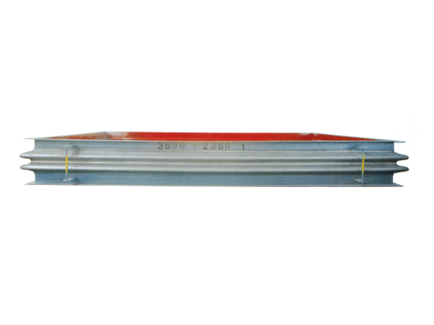
Metal rectangular expansion joint
Product introduction of metal rectangular expansion jointProduct Structure and C...
Learn more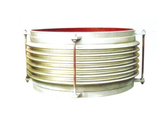
Universal corrugated expansion joint
The universal corrugated expansion joint is a kind of flexible compensation elem...
Learn more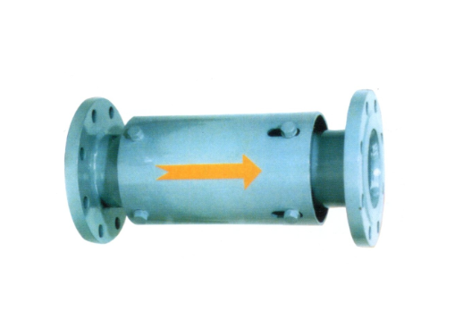
Single axial expansion joint
I. Structural compositionThe single axial expansion joint is mainly composed of ...
Learn moreCompensator, baffle door equipment · One-stop service process
From consultation to installation, we offer a full range of professional services
Consultation needs
The professional team will provide you with detailed product consultation and technical support to understand your specific needs
Scheme design
Provide personalized product design according to your specific needs to ensure the best solution
Manufacturing
Adopt advanced production equipment and technology and strict quality control to ensure excellent product quality
Installation and commissioning
Professional technicians provide on-site installation and commissioning services to ensure the normal operation of the equipment
About Us
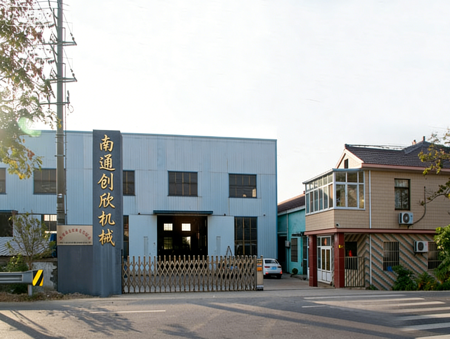
Nantong Chuangxin Machinery Co., Ltd. is located in the plain of central Suzhou, close to Nantong and Ningjingyan Expressway with convenient transportation, and less than 2 hours drive from Shanghai, Suzhou, Wuxi, Nanjing and other large and medium-sized cities.
The company is a comprehensive scientific and technological enterprise integrating design and development, production, product sales, installation and debugging. The company has successively communicated and cooperated with the National Cement Research Institute and the general contractor!
The company's main products are metal compensator (expansion joint), non-metal compensator (expansion joint), baffle door and other series products, providing excellent and cheap complete sets of equipment for the majority of users at home and abroad.
NEWS
Stay up-to-date with company and industry updates
What exactly is the use of the metal expansion joint internal baffle? It makes a big difference if you install it or not
First, find out the position of the internal baffle in the expansion j...
How to choose composite metal expansion joint? Let's look at these five doors first
In recent years, composite metal expansion joints have appeared more a...
Metal expansion joint telescopic rod, selection is not only as simple as length
When I met many customers who did pipeline design, I asked, "How long ...
What is the skin on the outside of the metal expansion joint for?
First distinguish: the skin of metal expansion joint and non-metal exp...
What is the metal expansion joint medium piece? Understand its function, material and selection
Let's start with the structure: What is the role of the medium film?Th...
Corrugated expansion joint of metal steel strip: from structure to type selection, explain the doorway clearly
What exactly is the corrugated expansion joint of metal steel strip? F...
Frequently asked questions
Answers to your frequently asked questions about compensators and baffle doors
1. What exactly is the expansion joint carrying at the entrance? — — The working condition determines the selection direction
The expansion joint at the entrance of the horizontal flue of the absorption tower looks inconspicuous, but it is actually one of the most gas-receiving positions in the whole desulfurization system. Think about it, the temperature of the original flue gas from the inlet flue followed by the boiler is high and low, and the desulfurization tower is an acidic wet environment. The expansion joint should not only absorb the displacement caused by the sinking of the tower body, but also bear the thrust of thermal expansion and contraction of the horizontal flue. If you choose the wrong choice, you can leak air and slurry, or crack the tower wall. Don't ask me how I know. I've seen too many at the maintenance site.
Therefore, the first step is not to turn over the samples, but to list the working conditions clearly: What is the flue gas temperature? How high is the sulfur content? Is there a possibility of backward flow of slurry? What is the approximate settlement of the tower body? Is pipeline design pressure positive or negative? There is a point that is easy to overlook here-the inlet of the desulfurization tower is generally negative pressure, but positive pressure impact may occur at the instant of starting and stopping the furnace. If this is not considered when selecting the expansion joint, the ripples will be reversely damaged.
Second, metal or non-metal? Don't pat your head, look at the temperature and the medium
"Do you have a metal rectangular expansion joint?" I usually ask back: Is the temperature of your inlet flue above 200℃? Is there any condensation of corrosive media? Non-metallic expansion joints (fabric fiber expansion joints) tend to be more suitable if the perennial operating temperature is below 120°C and there is a risk of sulfuric acid dew point corrosion. It is not afraid of acid and alkali, has a large amount of displacement compensation, and can reduce vibration and noise. On the other hand, if the temperature exceeds 250℃, or the particulate matter in the flue gas is seriously eroded, metal rectangular expansion joints or stainless steel corrugated structures are necessary.
Both structures have their own destinies. The fabric layer of non-metallic compensator is a consumable, which generally needs to be replaced in three or five years, but the price is cheap and easy to replace; Metal can withstand high-temperature abrasion, but once chloride ions exceed the standard, pitting corrosion will be worn. It is not that metal must be advanced, it depends on whether there is a large amount of halogen in the flue gas component. The flue gas at the inlet of the desulfurization tower is not so clean.
3. Displacement, pressure and caliber-all three parameters are indispensable
When selecting, many people only quote one diameter size, such as "2m ×3m rectangular flue", and then wait for a quotation. That's not gonna work. If one of the three core parameters is less, the supplier can only give you an estimate. In the end, it can't be installed on site.
The first is the amount of displacement. The settlement of the tower body generally gives the vertical displacement, the thermal expansion of the horizontal flue gives the axial displacement, and the lateral swing caused by wind load. You have to give the axial, transverse and angular displacement requirements respectively, such as "±30mm axial and ±15mm transverse". Without this number, how to determine the number of layers of non-metallic expansion joints? How to calculate the wave number of metal ripples?
The second is stress. Don't just say "negative pressure 3000Pa", but tell the designer what the maximum positive pressure is. Under negative pressure conditions, the expansion joint is easy to be deflated, so it is necessary to add an internal support skeleton; The pressure bearing capacity of the corrugation is tested when the positive pressure impact is carried out. Therefore, the pressure parameters must be written in full: negative pressure in normal operation, positive pressure in abnormal working conditions, and full pressure of fan.
The third one is caliber – it's easiest to step on pits here. Rectangular flue is not only width and height, but also inner diameter or outer diameter, flange connection or insertion welding. You only gave a "4 meters long and 3 meters wide", and they did it according to the outer diameter. When they went to the scene, they found that it was larger than the flue, and they had to cut it on the spot. Is it troublesome?
4. The easiest pits to step on in the installation and maintenance links
Everything will be fine when the expansion joint is installed? Thinking too much. I have seen this scene several times: when hoisting, the wire rope is directly strangled on the bellows, and the corrugated pressure is deformed and unknown; Or forget to remove the transportation protection tie rod when installing, and the expansion joint is locked tightly, so no displacement can be made up. Therefore, the first thing when you arrive, check whether the transportation bracket has been disassembled, and don't take a "tightening curse" to work.
In addition, the direction of the guide tube must be opposed to the direction of the medium flow. Install backwards, the smoke directly washes the root of the corrugation, and it will leak soon. There is also a pit in the non-metallic expansion joint-the insulation cotton is damp. During installation, if the surrounding welding operation is not blocked, the welding slag falls into the fabric layer, or rainwater pours back into it, the insulation layer fails, and the outer skin will quickly burn through. The same is true during maintenance. Before changing the non-metallic ring belt, be sure to clean the old bolts and polish the sealing surface smoothly, otherwise it will leak no matter how tight it is.
Another point, try not to install other supports and hangers near the expansion joint. The constant force hanger of the horizontal flue should be arranged on the other side of the expansion joint, otherwise the compensation amount will be eaten by the support hanger. Isn't it installed for nothing? If you want to understand these questions, then go to the manufacturer to talk about the selection, and the reported scheme is reliable. After all, the selection of the expansion joint at the inlet of the horizontal flue of the absorption tower is never to copy the operation according to the model, but to chew the working conditions and feed them to the designer, so that he can hand over qualified parts to you.
Find out what layers of materials are made of non-metallic expansion joints first, and stop asking layman questions such as "which material is best"
Two days ago, I met a customer and asked, "Which material is the best for your non-metallic expansion joint?" I was stunned for a moment and asked him, "How many degrees does your pipe run? How many MPa is the pressure? Is there any corrosive medium?" He couldn't answer. This question itself is wrong-non-metallic expansion joints never depend on a single material to dominate the world, but multi-layer composite structures work together. You take apart a typical non-metallic expansion joint (also called a fabric fiber expansion joint). From the inside out, it is roughly: a fluoroplastic/rubber sealing layer, a ceramic fiber or glass fiber insulation layer, a wire mesh or fabric reinforcement layer, and a weather-resistant rubber/fluororubber protective layer on the outermost layer. Each layer does each layer of work, and as soon as the temperature changes, the scenes of each layer of materials have to be rearranged. So don't ask "which is the best", ask "what temperature range is your working condition in" first.
Normal temperature to 200℃: Performance boundary and typical application scenarios of rubber and fluoroplastic materials
This interval is the comfort zone for rubber compensators and PTFE compensators. For ordinary EPDM and neoprene, it is not a big problem to carry 120℃ for a long time, and it can be tolerated to rush to 150℃ in an instant. But if you expect the rubber to remain elastic above 150℃, you are rogue-the rubber will harden, crack, and even carbonize. On the fluoroplastics side, PTFE (polytetrafluoroethylene) has a temperature resistance of over 200℃, which is excellent in corrosion resistance. However, it has large creep and poor resilience, so it is usually made into a lining or composite layer, which does not bear force alone.
In actual projects, the most common ones from room temperature to 200℃ are flue gas pipes, ventilation pipes and low-temperature water vapor pipes. Choose rubber PTFE compensator or non-metallic expansion joint. The key is to see whether the medium is corroded. There are acid and base gases? The inner layer must be covered with PTFE or fluoroplastic. No corrosion? A regular rubber compensator is enough, cheap and durable. There is no metaphysics in this area, just don't overheat.
200℃ to 400℃: the true performance of silica gel, fluororubber and PTFE composite layers, which parameters will suddenly deteriorate?
Above 200℃, ordinary rubber is basically out. The only materials that can be applied are silica gel, fluororubber (FKM), and PTFE composite layers. But you think they can easily carry it to 400℃? Naive.
The continuous use temperature of silica gel generally reaches 250℃, and it can rush to 300℃ in a short time. However, after exceeding 250℃, the mechanical properties of silica gel drop from a cliff-the tensile strength and tear strength drop so much that you doubt your life. The temperature resistance of fluororubber is slightly better than that of silica gel, and it can reach 250℃-280℃ for a long time. However, when it exceeds 300℃, it begins to defluorinate, releasing corrosive gas, and when it is superimposed with acidic medium, the aging speed takes off directly. PTFE, in theory, can be used continuously at 260℃, but it creeps greatly at high temperature and high pressure, and PTFE will release a very small amount of fluorine above 260℃, which is a disaster for some precision equipment.
Therefore, in this interval, real engineers will make a "composite layer": ceramic fiber or glass fiber is used as the thermal insulation skeleton inside, fluoroplastic film is attached to the medium side, and then silicone or fluororubber is used as the outer seal. Many of the non-metallic expansion joints (fabric fiber expansion joints) you see are of this structure. The core of this interval material selection is not which material to choose, but how to combine it. One parameter is most susceptible to sudden deterioration: interlaminar adhesion. When the temperature is high, the adhesive fails first, the layers break off, the expansion joint bulges, and then the whole is scrapped. When selecting, be sure to ask what bonding process the manufacturer uses, and don't just look at the temperature-resistant paper data.
Above 400℃: Temperature Resistance Limit and Failure Mode of Ceramic Fiber, Glass Fiber and Wire Mesh Reinforcement Layer
Above 400℃, polymer materials are basically destroyed, leaving inorganic fibers and metals. Ceramic fiber is the protagonist, with long-term temperature resistance above 1000℃, while glass fiber is slightly lower, but it is stable at 500℃-600℃. The real bottleneck lies in the sealing layer: it is impossible to use rubber or fluoroplastics at this temperature, and it can only be laminated into a "metal-non-metal composite" by wire mesh + ceramic fiber, which is called metal mesh-reinforced non-metal expansion joint in China.
The failure mode has also changed. Low temperature is aging cracking, high temperature is fiber pulverization and wire mesh oxidation. What are ceramic fibers most afraid of? Thermal shock-the fiber breaks and pulverizes and falls off when the temperature changes suddenly. Wire mesh is obviously oxidized when it exceeds 500℃, especially in flue gas with sulfur and chloride ions. Corrosion + oxidation are combined, and the life is directly cut in half. Therefore, the surface of non-metallic expansion joints above 400℃ is usually coated with high-temperature resistant coating (such as aluminosilicate coating) to separate oxygen from corrosive media. In addition, do not neglect the thickness of the insulation layer in this temperature range. Some manufacturers make the insulation layer thin in order to save costs. As soon as the thermal bridge effect comes out, the outer surface is hot, and the metal flange may be deformed.
Comparison table of type selection in different temperature intervals: from flue gas duct to high temperature air duct, direct copy of material selection logic
If it is not completed, go directly to the table:
- ≤150℃: Ordinary EPDM, neoprene, used in flue gas pipeline, dust removal pipeline. Typical Product: Rubber Compensator.
- 150℃—200℃: PTFE lining + rubber outer layer, or fluororubber integral molding to deal with weak corrosive media. Typical products: PTFE compensator, rubber PTFE compensator.
- 200℃—350℃: Silicone/fluororubber + glass fiber composite layer, suitable for hot air duct, boiler flue. Typical products: Non-metallic expansion joints (fabric fiber expansion joints).
- 350℃—600℃: Ceramic fiber + glass fiber + wire mesh reinforcement, outer layer with high temperature resistant coating. Suitable for high temperature air duct and power station flue gas system.
- >600℃: All-ceramic fiber layer + metal mesh interlayer, and the inner layer is even superimposed with refractory castable. This kind of working condition generally has to be customized, and conventional products can't do it.
The higher the temperature, the thinner the sealing layer, the thicker the insulation layer, and the denser the reinforcement layer. You see those rectangular non-metallic expansion joints, with large cross-sections and many layers. They are not showing off, and each layer is forced out by working conditions.
In addition to material selection, it also depends on the working conditions: how do pressure, corrosive medium and displacement affect the upper limit of temperature?
Temperature is just the ticket, and what really determines lifespan is the superposition of three things.
Number one, stress. The higher the pressure, the easier the material is to be "topped" out of the bulge. In the same 250℃ working condition, the material selection of 1kPa flue gas pipeline and 50kPa compression air duct is completely different. Under high-pressure working conditions, even if the temperature is not high, part of the temperature resistance must be sacrificed to change the strength-for example, the number of wire mesh layers must be increased, because the fiber layer is compacted as soon as it is compressed, the heat insulation effect decreases, the "internal conduction" of temperature intensifies, and the surface material ages faster.
Second, the corrosive medium. Sulfur oxides and chloride ions in flue gas can corrode and crack stainless steel mesh at 200℃, let alone fluororubber. When encountering acidic medium, inner PTFE is almost necessary, but the temperature resistance of PTFE is limited. At this time, you have to struggle: Do you keep temperature resistance or anti-corrosion? The realistic approach is to adopt the gradient structure of "multi-layer PTFE + ceramic fiber", so that PTFE only faces the medium side, and the temperature is blocked by the heat insulation layer. Doesn't it sound simple? However, many small factories can't do a good job in interlayer compounding, and they are delaminated after a period of time.
Third, the amount of displacement. The advantage of non-metallic expansion joint is large displacement compensation, but the displacement amount is too large, the fiber layer bends repeatedly, and the fatigue fracture is faster than over-temperature. Especially at high temperature, the ceramic fiber itself is brittle, and then superimposed with frequent displacement, the fiber pulverization speed doubles. Therefore, in the case of large displacement, it is necessary to increase the thickness of fiber layer or adopt corrugated fabric structure instead of simply stacking materials.
Have you noticed? The performance comparison of non-metallic expansion joint materials in different temperature ranges finally requires "working condition selection". Simply asking what degree of temperature resistance is as amateur as asking "which material is the best". Next time, choose the non-metallic expansion joint. First, throw the four cards of temperature, pressure, medium and displacement to the manufacturer, and let the manufacturer arrange the composite layer structure for you. If the manufacturer only reports a temperature resistance number, this product can't be asked for.
Let's talk about the temperature first: it's not just filling in a number
Two days ago, a customer came to me with a purchase order that said "temperature 200℃" and asked me if I could do it. I asked him back: Is this 200℃ the medium temperature or the design temperature? Steam pipes or thermal oil? Is it a continuous 200℃ run or an occasional flush? He was stunned for a moment and said, "This…the manufacturer asked me to fill it in."
And the result? Less than two months after installing the equipment, the bellows leaked. When disassembled, the material has creep cracks. The problem is not the manufacturer, but the "200℃"-he filled in the medium temperature, but the design temperature required for model selection is the highest temperature of the medium plus the safety margin, which is dozens of degrees different. How to write compensator selection temperature? If you really think you can just fill in the numbers, then there are pits behind.
First thing: The three temperatures must be clearly distinguished
Medium temperature, design temperature, and ambient temperature are three things, not the same thing.
Medium temperatureIt is the actual degree of fluid in the pipe, which is easy to understand.Design temperatureIt is the highest temperature that the compensator can bear. When selecting the model, the highest temperature of the medium plus the safety margin is taken-for example, the highest operating temperature of the steam pipeline is 250℃, and the design temperature is at least 280℃ or even 300℃.Ambient temperatureIt is the external environment. Outdoor pipelines are exposed to minus 20℃ in winter and 60℃ in summer, which affects the selection of insulation layer and material toughness.
Many people just write the medium temperature and are done. The design temperature is not written, the ambient temperature is not mentioned, and the manufacturer can only guess. If you guess right, you are lucky. If you guess wrong, whose equipment is scrapped?
The second thing: Metal and non-metal, the way to write temperature is two sets of logic
Metal corrugated expansion joints (such as general corrugated expansion joints and high-temperature axial expansion joints) absorb displacement by elastic deformation of corrugated shell, and temperature directly determines the allowable stress of material. 304/316L can hold up at room temperature, and above 400℃, the allowable stress is visible to the naked eye. At this time, either change the alloy material with higher temperature resistance, or increase the number of layers or wall thickness to compensate for the strength loss. Therefore, when selecting the metal compensator, the temperature should be clearly written as "maximum operating temperature", and whether there is an instantaneous overtemperature condition should be indicated-for example, when the steam pipe is heated, it may instantly rush above the design value, which directly affects the fatigue life.
The temperature resistance of non-metallic expansion joints (fabric fiber expansion joints, rectangular non-metallic expansion joints) depends on the skin material. Silicone coated glass fiber cloth, polytetrafluoroethylene film, ceramic fiber felt, each material has different temperature resistance upper limit: fluororubber can only reach around 200℃, and ceramic fiber can reach above 1000℃. Selecting and filling temperature of non-metallic expansion joint, you can't just write an average value. You have to write clearly the sustained temperature, peak temperature and duration-the non-metallic skin burns through this thing, which is often caused by instantaneous overtemperature, not slow aging. It looks reasonable for you to write "350℃". In actual working conditions, the bypass rushes to 600℃ for half an hour, and the skin burns through directly. Whose do you think this belongs?
Third thing: Temperature and pressure are bound, don't disassemble and write
The same general-purpose corrugated expansion joint can withstand 2.5MPa at room temperature, and may not even be able to withstand 1.0MPa at 400℃. When the temperature is high, the yield strength of the material decreases and the creep rate accelerates. Therefore, the temperature and pressure in the selection parameter table must be paired: "200℃/1.6MPa" and "400℃/0.6MPa"-this is called working condition pair, not two separate numbers. If only one temperature is written without the corresponding pressure, the manufacturer can't calculate the fatigue life and stability at all.
And the temperature cycle frequency. Alternating hot and cold several times a day is completely different from starting and stopping only once a year, and the fatigue life calculation is completely different. Each time the steam pipeline starts and stops is a temperature cycle, and each cycle of the bellows consumes a fatigue life. When writing the temperature, write the working system clearly: continuous operation or intermittent operation, and start and stop several times a day. It's much more important than struggling with those few degrees of error.
Fourth thing: Case is straightforward than theory
Some time ago, a cement factory purchased a non-metallic expansion joint for the flue gas pipeline. The working condition table wrote "temperature 350℃", which looked fine. I asked: Is there an instantaneous high temperature in the kiln tail flue gas? He said that yes, when the kiln is shut down for maintenance, the bypass is opened, and the flue gas temperature can rush to 600℃ for about half an hour.
That's the key message. The material cost difference between the skin selected according to 350℃ continuous and 600℃ instantaneous working conditions is more than double that of the material selected according to 600℃ continuous working conditions. If the communication is not in place, the manufacturer will continue to design according to 600℃, and you will spend 600℃ money; The manufacturer designs according to 350℃, and what you get is 350℃ goods, which will be burned through as soon as the bypass is opened.
Practical suggestion: Write this in the temperature column of the selection single
Don't bother, just fill in these:
- Medium temperature range: xx℃ ~ xx℃
- Design temperature: xx℃
- Instantaneous maximum temperature: xx℃/duration xx minutes
- Ambient temperature: xx℃
- With or without insulation: Yes/No
If you are not sure, ask the manufacturer directly, explain the working conditions thoroughly, and let the other party help you judge. Compensator is a waste of money if you choose it big, and a safety hazard if you choose it small. Only when the temperature parameters are written accurately can the equipment be installed and used for a long time. How to write compensator selection temperature? The answer is four words: write the whole working condition.
Find out one thing first: Does big thermal expansion test the bellows or the frame?
When many people talk about expansion joints, their eyes are fixed on the bellows-how good the material is, how much the wavenumber is, and how much the temperature resistance is. But have you ever thought that the bellows are cracked and crushed. In many cases, it is not the bellows itself, but the frame can't hold it first. If the frame is not hard enough, the bellows will be completely messed up under the force, and no matter how good the stainless steel bellows is, it will be in vain.
To put it bluntly, in the face of great heat expansion, the frame is the one who carries the matter. The bellows is responsible for deformation and absorption of displacement, and the frame is responsible for restraining the messy forces such as blind plate force, internal pressure thrust and thermal stress. The frame broke down, and the bellows were the scapegoat.
Three mainstream choices of profile frames: carbon steel, stainless steel and non-metal composite frames, each with its own destiny
Carbon steel, stainless steel, non-metal composite. Carbon steel is cheap and high in strength, but its temperature resistance is limited. If it exceeds 350℃, alloy steel or lining with heat insulation layer must be applied. Stainless steel is good in temperature resistance and corrosion resistance, but it is expensive, and the stiffness will drop at high temperature, depending on the specific grade. What about non-metallic composite frames? Light weight, strong corrosion resistance, but weak pressure bearing capacity, generally used in low pressure and large cross-section smoke duct occasions.
Choosing a frame is not the more expensive the better, but to see who can hold the bottom line at what temperature and load. When you take the carbon steel frame to carry the smoke at 800℃, it will be oxidized and peeled in two days, the stiffness will plummet, and the bellows will suffer.
Take the power station and cement industry to talk about things: How to choose the frame of high-temperature axial expansion joint and metal rectangular expansion joint
The flue at the tail of power station boilers and cement kilns can expand by tens or even hundreds of millimeters. This kind of place is commonly usedHigh temperature axial expansion joint, the bellows are Inconel or high nickel, but what about the frame? Many design institutes only give a Q235B channel steel, as long as it is strong enough. And the result? After half a year of operation, the frame was deformed, the bellows was forcibly twisted and pulled, and the weld cracked.
Metallic rectangular expansion joints in the cement industry are more typical. The stiffness of the rectangular section itself is poor. If the frame is not reinforced by box girders or stiffened plates, the out-of-plane deformation will directly press on the bellows as soon as the internal pressure comes up. Two days ago, I met the owner of a cement factory, saying that their flue expansion joint had changed the bellows three times a year, and then it was replaced with an integral stainless steel frame with reinforcing ribs, and there was no accident.
What happens if the frame is not stiff enough? Measured data tell you the common reasons why bellows are cracked
The axial expansion joint of DN500 has a design pressure of 0.25MPa and a temperature of 600℃. The frame is made of No. 14 channel steel and the bellows stiffness is 120N/mm. During operation, the thermal displacement is 60mm, and the lateral deformation of the frame reaches 8mm. As a result, the actual bending stress of the bellows is 40% higher than the design value-the fatigue life is directly cut by half. There are a lot of cases in the air duct and desulfurization pipeline of power stations.
The bellows were pulled and cracked, and eight out of ten were caused by frame deformation. You think that the quality of the bellows is not good, but in fact, the stiffness of your frame is not enough. During the design, only the strength was checked, but not the stiffness. When the frame is bent in the hot state, the bellows is not pure axial compression, but the composite force of tension + bending + torsion. Who can bear it?
Don't just look at temperature resistance, but also look at the restraint mode-tie rods, hinges, pressure balance, and the frame structure changes accordingly
What material to choose for the frame is one thing, the structural form is another. Tie rod expansion joint, the frame to bear the reaction force from the tie rod, then you have to calculate the buckling of the tie rod and the strength of the connecting ear plate. Hinged type, hinge seat must be installed on the frame, the force points are more concentrated, and the local stiffness requirements are higher.
The pressure balance type is more complex, such asStraight pipe pressure balanced expansion jointOrCurved tube pressure balance expansion jointThe forces of the middle bellows and the balanced bellows should be self-balanced through the frame. If the frame stiffness of this structure is insufficient, the bellows are involved with each other, and it is easy to become unstable. Do you think the frame is nothing more than a few steel plates welded together? When it was actually designed, it was full of doorways.
Type selection suggestions: What working conditions use carbon steel frame and what working conditions must use stainless steel or non-metal frame
The flue gas temperature is lower than 350℃, the pressure is not high, the medium is not corrosive, and the carbon steel frame is enough, but remember to add coating or temperature-resistant paint. If the temperature exceeds 400℃, or there is sulfide corrosion (such as the flue behind the desulfurization flue gas baffle door), don't hesitate to use a stainless steel frame, at least 304L, and 316L or higher for the high-temperature section.
For large-diameter rectangular flue, such as cement kiln tail and power station induced draft fan outlet,Rectangular non-metallic expansion jointIt was more appropriate at this time. The non-metallic expansion joint itself absorbs the displacement by fabric fibers. The frame is made of non-metallic composite materials or carbon steel frames lined with stainless steel, which is light in weight and corrosion resistant. The key is that the cost is much lower than that of all stainless steel.
Let's talk moreMetal rectangular expansion jointThis kind of dust collector used in the import and export of power plants, the frame must be made of reinforcing ribs, and it is best to weld hot-rolled steel into an integral frame, instead of welded thin-walled steel plates. Don't ask me how I know – I've seen too many cases of rectangular corrugated plates tearing due to insufficient frame rigidity.
So, back to the question at the beginning: What profile frame can eat big heat expansion? The answer is: a frame with sufficient rigidity, right material and smart structure. Don't just focus on the bellows. If you choose the right frame, the expansion joint can be really worry-free. Next time a manufacturer blows to you that "our bellows use imported materials", you should ask first: What materials do you use for your frame? How do you check the stiffness? If he can't answer it, you know it.
The expansion joint leaks, which is upsetting to watch and more troublesome to deal with. But don't rush to dismantle it, first find out where the water came from. The location of the leakage point is different, and the reason is completely different from the modification of the method.
First distinguish the leakage point: bellows, weld, flange or connection
Get a leaky expansion joint and turn around it first. Water stains, rust, crystalline salt, will help you guide the way. There are only four common leakage points: bellows body, circumferential weld, flange sealing surface, and the connection between pipe and pipe.
Bellows leaks, usually with pinholes, cracks, or corrosion pits in the walls. Weld leakage mostly occurs on longitudinal seams or annular seams. If you look closely, you can find pores and unfused. Flange leaks, usually at the gasket position, with wet marks or dripping. As for the leakage of the pipe, it is often where the pipe butts with the expansion joint, and there is a problem with the weld or thread. And guess what? Many users report for repair and say that "the expansion joint is leaking", which is actually a flange leak, which has nothing to do with the half dime of the bellows.
Corrugated pipe leakage: corrosion, fatigue and stress corrosion cracking are the main causes
The bellows is the heart of the metal expansion joint. If it leaks, the problem is usually more serious. Three conditions are the most common.
The first is corrosion. There are chloride ions, sulfide in the medium, or improper chemicals are used during cleaning, and the inner wall of the bellows will pitting and intergranular corrosion. 304 stainless steel is very fragile in chlorine-containing environment, so you have to change 316L or higher grade material at this time.
The second is fatigue. The pipeline expands and contracts repeatedly, and every time the bellows expands and contracts, the corrugated root bears alternating stress. The number of cycles is more, and the crack will initiate from the trough and slowly penetrate the wall thickness. In particular, it should be noted that the constraints underground are more complicated than those above ground, and the fatigue life may be much lower than the design value.
The third is stress corrosion cracking. If the tie rod nut is adjusted too tightly and forcibly matched during installation, the bellows will take on duty with extra stress. If you encounter corrosive media again, the crack will break through in a few days. Here is a data: the 304 bellows of the circulating water pipeline of a power plant leaked after less than eight months. After metallographic analysis, it shows transgranular cracks and typical stress corrosion. Later, it was replaced with 254SMO material resistant to chloride ions, and the problem was solved.
Leaky welds and flanges: improper installation, loose bolts and gasket failure
Weld leakage is most likely a problem of welding quality. In the ring seam between the bellows and the connecting pipe, if the current is too large during welding, the welding wire is damp, or the slag is not thoroughly cleaned, there will be pores and slag inclusions. This kind of leakage point, all defects must be dug out before repair welding, otherwise it will be repaired in vain.
Flange leakage, don't blame the gasket yet. Check the bolts first. Have you ever encountered this situation: tightening the bolts a few turns, it didn't leak at the time, and then it leaked again two days later? That's because the flange is unevenly stressed, one side is crushed to death, and the other side is still open. The correct way to do this is to tighten diagonally, adding to the specified torque in two or three times. Gasket failure should be distinguished whether it is aging, creep or corroded by the medium. The rubber gasket quickly hardens in front of high-temperature oil products, so it can be held by replacing it with a metal winding pad or a PTFE pad.
The expansion joint was in use, and the weld between the connector and the pipe cracked. This is often due to the lack of pipe frame support in the pipeline system, and the expansion joint is regarded as a force bearing member. The expansion joint compensates for displacement, it is not responsible for load-bearing. The addition of sliding brackets is different.
Non-metallic expansion joint water leakage: fabric layer aging, skeleton corrosion and lax sealing
Don't think that only the metal expansion joints will leak. The non-metallic expansion joint (fabric fiber expansion joint) leaks, and the precursor is more concealed. It generally has several layers of structure: fluororubber or silicone coated cloth as airtight layer, ceramic fiber as heat insulation layer, and the outermost is stainless steel wire mesh and skin. Water seeped out, indicating that the airtight layer was broken.
Airtight layer aging is a common occurrence. The flue gas temperature fluctuates greatly, and the coated cloth alternates hot and cold repeatedly, and it begins to become brittle and cracked in about two years. If you notice powdery shedding on the surface of non-metallic expansion joints, that's a sign of aging. At this time, when it rains again, water seeps in along the fibrous layer.
Don't ignore skeletal corrosion either. The frames and platens of non-metallic expansion joints, if stainless steel, will still rust in sulfur-containing flue gas. If the platen bolts are rusty and the skin can't be pressed tightly, water will seep from the edges. The treatment method is to clean the bolts regularly, apply anti-jamming agent, and change to high-strength alloy bolts if necessary.
The problem of lax sealing mostly lies in the installation link. The sealant between the skin and the flange is not evenly applied, or the wave shape of the pressure plate is wrong, which will leave gaps. When installing, it must be pressed tightly according to the manufacturer's torque sequence. Don't try to save trouble and only screw a few points.
Treatment plan and prevention: explain from type selection, material to installation and maintenance
Water leaks are not done once and for all by plugging them. You have to hold it down from the source.
In the selection stage, first see the working conditions clearly. What is the medium? What's the temperature? How stressful? Is it corrosive? If it is a flue gas pipeline, it has to use non-metallic expansion joints (fabric fiber expansion joints) to absorb three-dimensional displacement, which is resistant to high temperature and has large compensation. If it is a steam pipe, metal corrugated expansion joints are more suitable, such as general purpose corrugated expansion joints or high temperature axial expansion joints, which can withstand higher pressures and temperatures. Wrong choice, it is only a matter of time before the water leaks.
In terms of material, for media with high chloride ion content, don't use 304, use 316L or 254SMO. When the temperature exceeds 400℃, stainless steel bellows should consider high-temperature creep. At this time, heat-resistant alloy can be selected. If the medium is particularly dirty and there are many particles, add a guide tube to avoid direct flushing of the bellows.
In terms of installation and maintenance, remember three things: First, the expansion joint tie rod nut, adjust it according to the requirements after installation, some need to be removed, some need to be loosened, don't screw it. Second, the flange connection should be symmetrically tightened and the moment should be uniform. The third is to make regular inspections, touch your hands and see, and find rust spots or wet marks, so deal with them as soon as possible. Small leaks do not make up, big leaks suffer.
In case of urgent work and no suitable spare parts on hand, can you temporarily block it? You can use pipe hoops and rubber plates to hoop the leakage point of the bellows first, but that is only an emergency and can't last for a month. What is really reliable is to replace the leaky expansion joint. Even if it is just a weld leak, it is recommended to replace it as a whole. Welding quality is such a matter, the site conditions are difficult to guarantee, and the risk of repair is much greater than that of replacing it with a new one.
Expansion joint leaks are no trivial matter and involve pipeline safety and production continuity. Distinguish the leakage points, see the working conditions clearly, choose the right products, and standardize the installation. After this set of combination boxing is played down, the probability of water leakage can be reduced by more than half. If you are annoyed by this matter, go through the above steps first, and there is a high probability that you can find out the root cause of the disease.
Contact Us
Your consultation and cooperation are always welcome
Company Address
Haian Economic and Technological Development Zone, Nantong City, Jiangsu Province
Contact Number
(+86)13142668488
info@jsbcq.net
Working hours
Monday-Friday :8:00 - 17:30
Saturday :9:00 - 16:00
Sunday :Rest