Specialized in manufacturing compensators, expansion joints, baffle doors
A comprehensive scientific and technological enterprise integrating design and development, production, product sales, installation and debugging
Specialized in the production of metal compensator, non-metal compensator, baffle door equipment for 18 years
Product Center
Specialized in manufacturing a variety of high-quality industrial equipment to meet your diverse needs
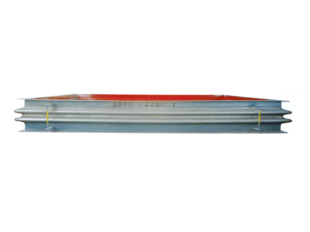
Metal rectangular expansion joint
Product introduction of metal rectangular expansion jointProduct Structure and C...
Learn more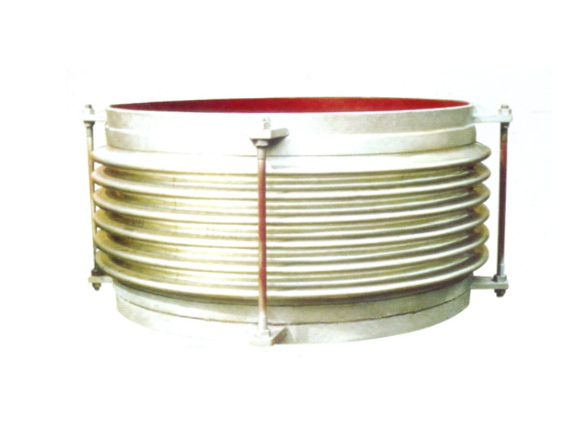
Universal corrugated expansion joint
The universal corrugated expansion joint is a kind of flexible compensation elem...
Learn more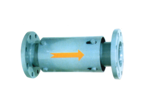
Single axial expansion joint
I. Structural compositionThe single axial expansion joint is mainly composed of ...
Learn moreCompensator, baffle door equipment · One-stop service process
From consultation to installation, we offer a full range of professional services
Consultation needs
The professional team will provide you with detailed product consultation and technical support to understand your specific needs
Scheme design
Provide personalized product design according to your specific needs to ensure the best solution
Manufacturing
Adopt advanced production equipment and technology and strict quality control to ensure excellent product quality
Installation and commissioning
Professional technicians provide on-site installation and commissioning services to ensure the normal operation of the equipment
About Us
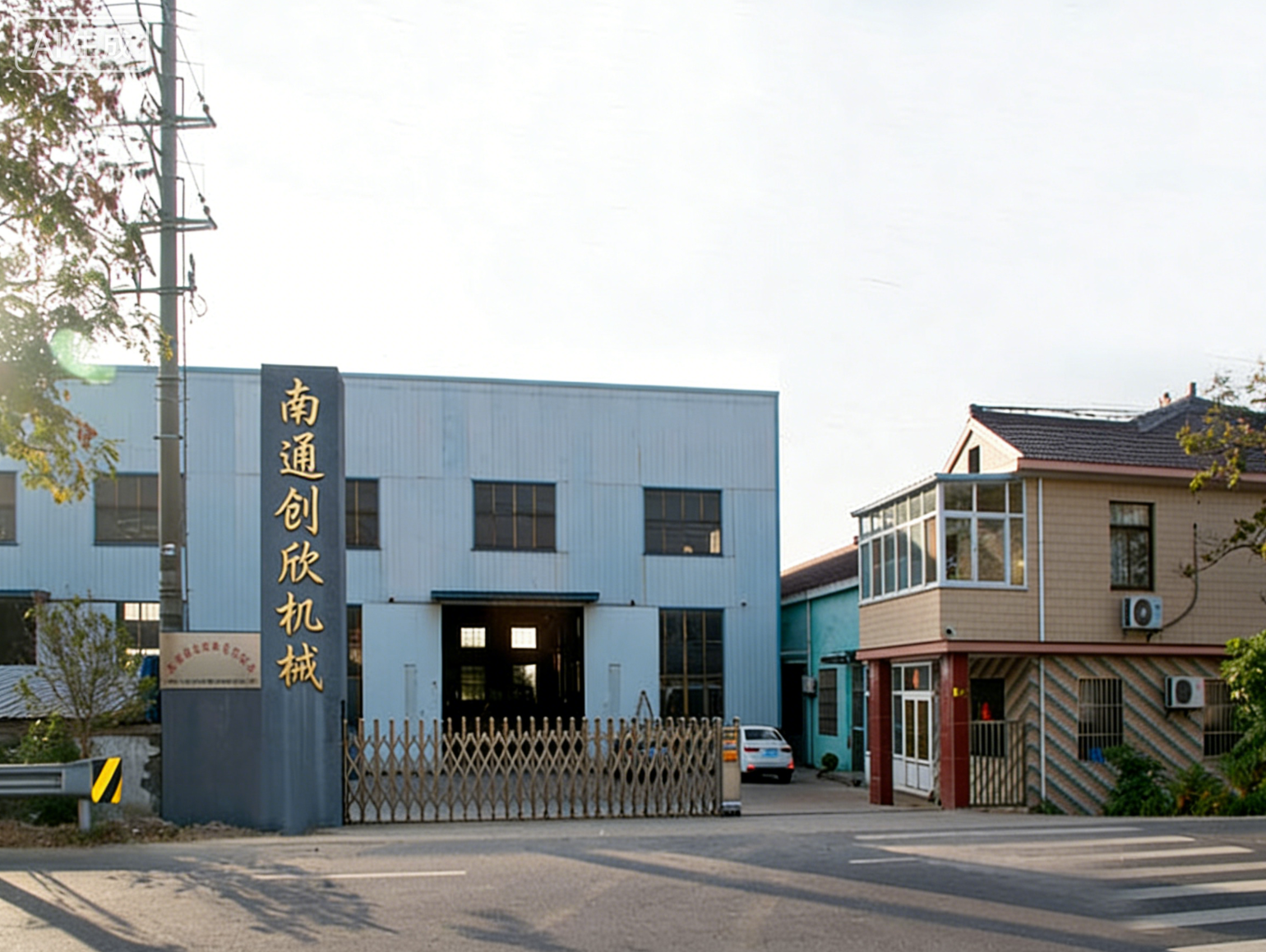
Nantong Chuangxin Machinery Co., Ltd. is located in the plain of central Suzhou, close to Nantong and Ningjingyan Expressway with convenient transportation, and less than 2 hours drive from Shanghai, Suzhou, Wuxi, Nanjing and other large and medium-sized cities.
The company is a comprehensive scientific and technological enterprise integrating design and development, production, product sales, installation and debugging. The company has successively communicated and cooperated with the National Cement Research Institute and the general contractor!
The company's main products are metal compensator (expansion joint), non-metal compensator (expansion joint), baffle door and other series products, providing excellent and cheap complete sets of equipment for the majority of users at home and abroad.
NEWS
Stay up-to-date with company and industry updates
Inner layer of metal expansion joint: the right material is chosen, and the life is doubled
Inner layer of metal expansion joint: the right material is chosen, an...
Detailed explanation of the function of metal expansion joint: compensating displacement, reducing noise and vibration, "flexible joint" of industrial pipeline
Metal Expansion Joint Function: Three Cores, None LessWhen talking abo...
How to choose metal hinge expansion joint? Don't get confused by the parameters
1. What is a metal hinge expansion joint? How is it different from ord...
Metal Non-standard Expansion Joints: Three Key Issues Must Be Clarified Before Customization
Why do you need "non-standard" expansion joints in pipeline systems? —...
Rubber metal expansion joint: What exactly is this thing, and how to choose it without stepping on the pit?
Two days ago, I met a customer, and when I came up, I asked: Is your r...
How to choose the form of metal expansion joint? Understand these five core structures first
"Old Zhang, our high-temperature steam pipeline needs to be fitted wit...
Frequently asked questions
Answers to your frequently asked questions about compensators and baffle doors
Mistaken selection is the number one killer of short lifespan-material and construction determine how many years you will last
Two days ago, I met a customer who complained that the expansion joint in their factory leaked after two years. When I removed it, the bellows were rotten. Ask about the working conditions-high-temperature steam pipeline, with a pressure of 1.6MPa and a temperature of 350℃. As a result, the general-purpose corrugated expansion joint was chosen at the beginning, and the material was 304 stainless steel. Isn't this seeking death?
The matter of model selection, to put it bluntly, is "what horse matches what saddle". High-temperature working condition honestly high-temperature axial expansion joint, the material must be Inconel 625 or at least 321 stainless steel; For corrosive media, such as desulfurization flue gas, you have to consider lining PTFE hoses or non-metallic expansion joints (fabric fiber expansion joints), and even rubber compensators can carry them for a while. In cases where particle erosion is serious, such as air ducts in cement industry, metal corrugated expansion joints in cement industry must have wear-resistant guide tubes, otherwise they will be worn out in less than half a year.
Structurally, don't be sloppy. For pipelines with large axial displacement, straight pipe pressure balance expansion joint or compound straight pipe bypass pressure balance expansion joint is the positive solution; If you need to absorb lateral displacement, compound hinge transverse expansion joint or curved tube pressure balance expansion joint is right. Choosing the wrong type is like letting a sprinter lift weights, and scrapping is a matter of time.
The "invisible killer" of the installation link: the draw rod is not adjusted in place, the guide tube is installed backwards, and no matter how good the expansion joint is, it is useless
You can sit back and relax when you choose the right equipment? That's naive. The pits in the installation link, each deeper than the last. The most common one is that the tie rod nut is not adjusted properly. The function of the expansion joint tie rod is to limit the over-stretching or over-compression of the bellows, but many installation teams directly lock the tie rod, or simply don't dismantle the transportation fixtures. And guess what? As soon as the pipeline heats up, the expansion joint has no space to compensate, and the bellows is directly bulged and scrapped. The correct way is to remove the transport screw after installation, and then adjust the tie rod nut according to the compensation amount. For details, refer to the article "How to adjust the tie rod nut of expansion joint" in our station.
There is a more hidden problem-the deflector is installed backwards. The specific function of the expansion joint guide tube is to guide the flow direction of the medium and protect the bellows from scouring. However, when the direction of the arrow is reversed, the medium directly impacts the root of the bellows, and the rate of corrosion and wear doubles. Remember: The direction of the arrow must coincide with the direction of the media flow. Don't laugh, at least 30% of the installers on the site will make this mistake.
Wear and corrosion in operation: medium temperature, particle erosion, chemical attack, how many of these pits have you stepped on?
During normal operation, the expansion joint can't be laid flat just by installing it. If the medium temperature exceeds the design value of 10℃, the fatigue life of the bellows may be directly discounted by 50%. Particle scour? That's even more like cutting meat with a soft knife. Some cement plants use ordinary metal rectangular expansion joints, and there is no guide tube inside. After half a year, the wall thickness of the bellows is ground from 3mm to 0.5mm. Do you think it can be perforated?
Chemical attack is more headache. The acid condensate in the desulfurization system is a fatal blow to the metal bellows. At this time, either choose a PTFE hose or PTFE compensator, or use a non-metal expansion joint (rubber PTFE compensator is also OK), but we must pay attention to the rubber aging problem. By the way: Is there pitting corrosion and intergranular corrosion on the surface of the expansion joint in your factory? If so, it means that there is a problem with material selection, so change it as soon as possible.
Regular inspection is not a formality: corrugated pipe cracks, rubber aging, non-metal layer peeling, early detection and early treatment
Many factory inspections are to walk around with a flashlight and see nothing. In fact, there is a precursor to the failure of the expansion joint. Fine cracks or "orange peel"-like deformation appear on the surface of metal bellows, which indicates that it is close to the fatigue limit. Rubber compensator or non-metallic expansion joint, pay attention to whether the surface has hardened, cracked, or delaminated peeling. Especially rubber, affected by ozone and ultraviolet rays, has a life span of three to five years. When the time comes, it should be changed. Don't wait for it to leak before stopping.
Also, check for any changes in the pre-tightening forces of the tie rods and bolts. After the expansion joint has been running for some time, the tie rod may loosen, causing the bellows to offset. If the bellows is found to have eccentric wear marks, it means that the pipe support may sink or the compensation direction is wrong. Early detection and early adjustment, it's still too late.
Environmental factors alone? Heat preservation, support and drainage are done correctly, and the life will be doubled directly
Environmental factors are often overlooked, but are often the last straw that crushes the camel. For example, the expansion joint installed outdoors does not do heat insulation, and the metal brittleness increases at low temperatures in winter, so the bellows is easier to crack. Another example is the expansion joint on the steam pipeline. If there is no reasonable drainage design, the condensed water will accumulate at the trough, forming a "water hammer", which will impact and damage the bellows. How to solve it? Set a drain valve at a low position, or choose a sleeve-type pipe expansion joint with drain structure.
Support is also critical. The expansion joint itself does not bear the weight of the pipe, and guide brackets and fixed brackets must be set nearby. Many sites use the expansion joint as a pipe support, but as a result, the bellows is flattened and scrapped in three months. Think about it, is it worth an expansion joint worth tens of thousands of dollars to be scrapped in advance because several brackets worth several thousands of dollars were not done properly?
When to change hard bracing: Precursor judgment of failure and targeted prevention strategies
Expansion joints are not maintenance-free for life. If the following signals appear, change them quickly and don't take chances: First, the bellows has obvious cracks or perforations; Second, the fabric layer of the non-metallic expansion joint peels off in a large area, and the internal thermal insulation cotton or steel wire mesh can already be seen; Third, the surface of the rubber compensator is hardened to the point that it can't be pressed, or there are bubbles bulging; Fourth, the whole expansion joint is obviously distorted, which indicates that the displacement of the pipeline has exceeded the design range.
According to the medium characteristics and working conditions, select the right type in advance (such as special products such as corrugated expansion joints for power station industry, double hinge expansion joints for air-cooled island vacuum pipelines, etc.), strictly implement the specifications during installation, and regularly check and adjust in time during operation. If conditions permit, install displacement monitoring sensors at key positions, and watch the expansion and contraction of the bellows in real time, and you will have a bottom in your heart.
To put it bluntly, there are three words to prolong the life of expansion joints-select, install and raise. Choose the right thing, install it well, and maintain it diligently. To achieve these three points, it is not a dream to serve for more than ten years.
Non-metallic compensator leaking? Don't be in a hurry to change, try these steps to fix the leak first
I answered a phone call two days ago, and the customer said that the non-metallic expansion joint of their dust removal system began to smoke after half a year. When disassembled, the particulate matter in the smoke grinds a hole in the skin-this kind of thing is too common in cement and electric power industries. The non-metallic compensator (also called fabric fiber expansion joint) is leaking. Your first reaction is to replace it with a new one? Don't worry. Find out the leak point first. 80% of the cases can be fixed on site.
Where's the leak? Three common locations
Non-metallic compensator is used in flue gas pipeline and desulfurization system. The medium temperature is high and corrosiveness is strong, and the leakage is basically in three positions: one is the overlap joint between layers, the other is the sealing surface at the connection of flange, and the third is the riveting point or weld between the guide tube and the skin. And guess what? Many times it is not the skin itself that is broken at all, but the bolts are loose-the flange surface leaks, which can be solved by tightening. So the first step is not to rush to buy new pieces. First, take a flashlight and brush it with soapy water to see where the bubbles come from.
The medium contains sulfur or strong acid and alkali, and the sealing gasket becomes brittle after aging, and it will break when touched. At this time, you have to judge the type of leak: is it pitting perforation (small hole), sealing surface failure, or overall fatigue cracking? The countermeasures are completely different in different situations.
Preparation before mending leaks: Wrong material selection is equal to dry for nothing
Don't put any glue on it. This site hasrubber compensator、Rubber PTFE compensator、Non-metallic expansion jointAnd other products, leak repair materials must match the working conditions. High-temperature flue gas pipeline uses high-temperature resistant silicone rubber or fluororubber sealant, and ceramic fiber repair materials have to be replaced when the temperature exceeds 300℃. If the medium contains acid and alkali, use PTFE sealing tape, refer to this sitePTFE-lined hoseCorrosion resistance ideas.
Be sure to clean up before repairing the leak. Oil, dust accumulation and old glue layer have to be shoveled off to expose fresh substrate. Wipe it with acetone or alcohol, and wait until it is completely dry before starting. Otherwise, if you make it up, it will drop in two days.
By the way, if the flange surface leaks, check the bolts first-in many cases, it's just thermal expansion and contraction that causes loosening. Just take a torque wrench and re-tighten it according to the original torque. Don't get major surgery right up there.
Three Methods of Leakage Mending in Actual Combat
Method 1: Small perforations or cracks are patched with temperature-resistant cement + glass fiber cloth in multiple layers.Apply the glue to the break first, stick the cut fiberglass cloth, and then scrape it flat with a scraper to ensure that there are no bubbles. Apply one layer until it dries (usually 4-6 hours), then apply a second layer, at least three layers. Finally, brush a layer of temperature-resistant sealant on the outer surface to form a protective film. This method is suitable for perforations less than 20 mm in diameter.
Method 2: The local damage area is large, and the skin of the same material is cut and replaced.This site has ready-madeNon-metallic expansion jointSkin material, cut according to the damaged area, overlap width at least 50mm. Apply high-temperature-resistant adhesive to the overlap surface, and rivet and fix it with stainless steel press strips and self-tapping screws after pasting. Note that the spacing of the pressing strips should not exceed 150mm, and the riveting points should be staggered out of the original structural holes to avoid stress concentration.
Method 3: Total Outsourcing? Don't mess around.Someone asked if you could just wrap a metal compensator on the outside? No way. This site hasHigh temperature axial expansion joint、Universal corrugated expansion jointHowever, these metal parts are used for pipe displacement compensation, and their structure is completely different from that of non-metallic skin. Hard wrapping will limit thermal displacement, but accelerate damage. A more reliable way is to customize a short-joint non-metallic expansion joint to replace the damaged section. The size should match the original pipeline. Just provide the diameter, temperature, pressure and displacement when ordering.
Testing and routine maintenance after leak repair
It can't be put into operation directly after repairing, so do the airtightness test first. Brush soapy water or foaming agent on the repair area, introduce 0.05~0.1MPa compressed air (the design pressure of non-metallic compensator is low, so don't overpressure), and observe whether there are bubbles. If there is no air source, feel the air leak point with your hands after running, or use infrared thermal imaging to see the temperature abnormality-the temperature at the leak will be significantly lower.
Check the skin surface quarterly for blistering, delamination, and hardening. Especially in cement plants,Metal Corrugated Expansion Joints in Cement IndustryNext to the non-metal segment, dust wear is fatal. It is recommended to establish a ledger, record the location of each leak and the number of repairs, and accumulate data to judge when to completely replace it.
When should I give up patching and replace it with a new one?
If the same part is repaired more than twice, or the leakage area exceeds 30% of the total area, don't worry about it. The design life of non-metallic compensator is generally 3~5 years, and the aging will be accelerated by temperature, corrosion and mechanical fatigue. Also note that if the leak occurs in connection with this siteFlue gas baffle door、Electric plug-in insulation doorWhen connecting, consider whether the system vibrates too much. Vibration will cause fatigue cracking of the skin, which is useless. You have to install damping or switch to non-metallic expansion joints with reinforcing nets.
Don't save hundreds of dollars to make up for the leakage. As a result, the leakage expands and leads to the shutdown of production-the loss starts with tens of thousands of dollars. If you need to change, you will not lose money in the general ledger.
Metal expansion joint desoldering? Don't hurry to scold the manufacturer, the problem may lie in this
Two days ago, I met a customer who said that the metal expansion joint weld of their pipeline was cracked, and asked me if the quality was not good. Alas, who is not in a hurry when it comes to such things-media leakage, production line shutdown, or safety accidents. But let's say, don't rush to throw the blame on the manufacturer. For the problem of desoldering, we must first look at where the welding is located. Is it the bellows and end pipe connection? Or a deflector weld? Or is it a tie rod mount? The causes of desoldering in different positions vary a hundred and eighty thousand miles.
The cracking of the circumferential weld between the bellows and the end pipe is most likely due to fatigue or stress concentration. If the weld of the guide tube is cracked, it is mostly because the guide tube is worn through by the medium or the guide tube is installed backwards, causing the airflow to directly scour the weld. Tie rod bearing desoldering? You have to check whether the tie rod nut is loosened during installation, and whether the limit is regarded as a fixed support. And guess what? Many so-called "quality accidents" were checked over and over again. Either the installation team was fooling around, or the selection didn't match the working conditions at all.
The three most common pits for desoldering
First, fatigue.The pipeline system expands and contracts thermally every day, and the expansion joint expands and contracts repeatedly. Once the stress concentration at the weld exceeds the allowable value, cracks will slowly grow out. Especially the large-diameter thick-walled expansion joint or high-temperature axial expansion joint, the more extreme the working condition, the more sensitive the fatigue life. For example, the temperature of high-temperature flue gas pipelines in the cement industry often fluctuates above 400℃. Every time the bellows expands and contracts, the welds accumulate damage.
Second, corrosion.When there are chloride ions and sulfide in the medium, the weld seam will be corroded preferentially, and the strength will drop linearly. The expansion joint behind the desulfurization flue gas baffle door has a bad corrosion environment. If the right material is not selected or the corrosion resistance treatment is not done, the weld will become slag in less than half a year.
Third, the installation error.When leaving the factory, the tie rod nut was not loosened, the guide tube was installed backwards, and the cold drawing amount of the pipeline was not enough... These operations caused additional stress to be fully pressed on the weld. Many customers complained that "it took three months to desolder". As a result, when they went to the scene, they found that the direction of the guide tube arrow pointed to the opposite direction of the medium flow, and the airflow directly hit the bellows. Tsk, is this pot manufacturer wronged?
What about that?
Let's see the working conditions first. If it is a pipeline at normal temperature and low pressure, such as a general-purpose corrugated expansion joint, the cracking of the weld joint is probably a problem of the welding quality itself-the current is excessive, the welding electrode is wrong, and the groove is not handled properly. You have to re-weld if you should cut it off and re-weld it. Don't feel distressed. However, if it is a high-temperature steam pipeline or a high-temperature flue gas pipeline in the cement industry, desoldering is often a wrong selection. At this time, we have to consider changing the high-temperature axial expansion joint or the external pressure single axial expansion joint, so that the bellows can avoid the high-temperature area. Another situation: the displacement of the pipeline is too large, and the general-purpose type can't bear it at all, so it is necessary to use the double hinge transverse expansion joint or the straight pipe pressure balance expansion joint to share the stress.
On-site emergency treatment is also particular. Small cracks can be repaired in non-critical parts, but they must be welded with the same material electrode, preheated and controlled cooling speed. If the bellows itself is cracked, don't repair welding-the wall thickness of the bellows is thin, and it will burn through as soon as it is repaired, so replace it directly. In addition, it should be noted that before repair welding, check whether the guide tube is in good condition. If the guide tube is also worn out, the medium will directly wash the inner wall of the bellows, and desoldering is only a prelude. When replacing, it is best to check the adjustment status of the expansion joint tie rod nut simultaneously to ensure that the pre-tension or pre-compression meets the design requirements. As for how to adjust the tie rod nut? After screwing the nut to the limit position, reverse back half a turn to one turn, so that the expansion energy saving can expand and contract freely. Look at the design drawings for specific values, don't screw them blindly by hand feel.
Prevention is really worry-free
The selection stage is not cheap. When providing information to the design institute, write clearly the temperature, pressure, displacement and corrosive medium. For example, the expansion joint behind the flue gas baffle door has a high sulfur content in the medium, so corrosion-resistant alloy or PTFE-lined scheme must be used. In the installation stage, be sure to look at the direction of the arrow on the expansion joint (flow direction mark), and one end of the guide tube faces the direction of the medium. During the operation stage, check the appearance of the weld regularly, tap and listen to the sound, and do penetration testing if conditions permit. Don't forget, the life of the expansion joint is directly tied to maintenance-you let it run over the limit, and it will strike sooner or later.
In the final analysis, 80% of the desoldering of metal expansion joints are not deliberately cut corners by manufacturers. Find the root cause, prescribe the right medicine, change the type, repair the welding, don't curse your mother as soon as you come up. Pipeline safety depends on the cooperation of three rings of selection, installation and maintenance, and one less ring will lead to moths.
1. Where are non-metallic compensators used? Don't use it in the wrong place.
Non-metallic compensator (also called non-metallic expansion joint/fabric fiber expansion joint) is mainly used to deal with low-pressure and high-temperature pipeline systems such as flue gas, hot air and dust. To put it bluntly, where the metal expansion joint can't withstand high-temperature corrosion or large displacement, it should play. For example, the desulfurization flue gas pipeline of the power station, the kiln tail waste gas pipeline of the cement industry, the blast furnace gas pipeline of the steel plant, and even the flue gas purification system of the waste incineration plant-the temperature in these occasions is always five or six hundred degrees, and some instantaneous peaks can rush above 1000℃, and the metal parts are soft for a long time.
Unlike metal compensator, it relies on fiber fabric and rubber composite layer to absorb displacement, and does not generate thrust itself, which can save a lot of trouble in bracket design. But you have to put it on a high-pressure steam pipe? That is wrong-if the pressure exceeds 0.1MPa, you have to choose the type carefully, and don't use it as a high-pressure part. A customer in our station once wanted to use a rectangular non-metallic expansion joint on a 2MPa compressed air pipe, but before it even ran, the fabric layer bulged.
2. Find out these 4 parameters before installation, otherwise it will be in vain.
The first is the displacement-you have to calculate how many millimeters the thermal expansion and contraction of the pipe are offset, and calculate the axial, transverse and angular directions separately. Many on-site pictures save trouble, and they say "come to a 200mm one" when they open their mouths. As a result, the actual displacement is only 30mm, a small horse pulls a big cart, and the fabric folds age quickly. The second is the temperature-the highest temperature and instantaneous peak temperature of the medium directly determine which layer of fabric to choose: silicone cloth can withstand the temperature of about 200℃, fluorine cloth can reach 300℃, and ceramic fiber will be required if it is higher.
The third is the media composition. Have strong acids and bases? That has to be lined with PTFE, which is the "rubber PTFE compensator" or "PTFE compensator" on our station. The fourth is the installation space-rectangular non-metallic expansion joints for square pipes and rounds for round pipes, don't get confused. Two days ago, a customer welded a round one to a rectangular air duct. As a result, the seal was not tight and it took half a month to rework. You say it was wrong or not?
3. Installation steps and the details of the easiest rollover.
Hoist in place → Adjust bolt pre-tension → Weld or flange connection → Remove transport screw. But the worst thing about the rollover is-when will the transport screw be removed? Many people dismantle it as soon as it is installed, and as a result, the compensator is pulled out before the pipe is hot. Correct practice: Wait until the pipeline is installed, the bracket is fixed, and then disassemble it before trial operation. The FAQ of our station specifically mentioned "Does the screw of the expansion joint need to be disassembled?" That's what it said.
In addition, the direction of the guide tube must follow the flow direction of the medium, and the direction of the arrow should not be reversed. And guess what? A cement factory installed the guide tube backwards, and the high-temperature airflow directly washed the fabric layer, which was perforated in three days. We also talked in detail in the FAQ of our station that "the arrow direction of the expansion joint" is for this purpose.
4. In daily use, the three most easily overlooked pits.
Pit 1: Let the compensator bear the load.The non-metallic compensator only absorbs displacement and does not bear weight. The weight of the pipeline depends on the bracket. Even an elbow should be supported separately. Don't let it hang. Some site drawings save trouble, hang the valve directly on the compensator, and the flange leaks within a month.
Pit 2: Neglect insulation.The outer insulation layer not only insulates heat, but also prevents condensed water from corroding the fabric layer. However, many people think that "it can withstand high temperatures anyway" and don't pack it. As a result, the outside condenses and water seeps into the fabric, accelerating aging. Especially noticeable in winter.
Pit 3: Large compensator for small displacement.Some people choose oversized specifications for "insurance", which leads to wrinkles and accelerated aging of fabrics under low displacement. According to JB/T 12235-2015 standard, the working displacement of the compensator is preferably controlled between 60% and 80% of the rated displacement. You say that using a 200mm compensator to absorb a 20mm displacement, isn't that a waste of things?
5. When should I change? Don't wait until it leaks to dismantle it.
The life of a non-metallic compensator is usually 3-5 years, but depends on the operating conditions. If you find that the surface of the fabric layer is cracked, hardened, delaminated, or the flange bolt can't be tightened after it is loose (indicating that the sealing layer has collapsed), then you have to change it quickly. Another signal-the vibration of the pipe suddenly becomes louder, or there is an abnormal noise around it, which may be that the internal guide tube has fallen off. Usually check the appearance quarterly, focusing on welds and fabric overlaps.
If you want to save trouble, rubber compensators are cheaper than fabric compensators, but the temperature resistance is only about 100℃, so don't get confused. When encountering high-temperature flue gas, nonmetallic expansion joints (fabric fiber expansion joints) or rectangular nonmetallic expansion joints have to be used. In the final analysis, with the right selection, the right installation, and the maintenance keeping up, it is not a problem to use a compensator for five years.
What is radial force? Why do so many people fall on this
Anyone who designs pipelines knows that the biggest function of metal expansion joints is to absorb heat displacement. However, when the radial force was mentioned, many people began to be confused. Radial force, to put it bluntly, is the force that pushes the bellows perpendicular to the axis of the pipe, from the center outward or from the outside inward. Wrong direction, light bulge, worse bracket collapse, pipeline twist. Two days ago, I met a customer. A DN600 steam pipe was equipped with a universal corrugated expansion joint. As a result, the radial force was not calculated accurately. After three days of production, the corrugated pipe bulged like a toad's belly. Alas, this kind of thing is not rare.
Radial forces under internal pressure: Outward expansion is mainstream, but not so simple
As soon as the pressure inside the pipe comes up, the bellows expands outward like a balloon-this is the most intuitive direction of radial force, pointing from the central axis to the outer wall. But don't think it's just evenly outward. withUniversal corrugated expansion jointFor example, the radial force generated by internal pressure will make the wave peak expand outward and the wave trough contract inward. The magnitude of this force is directly related to the pressure and wave diameter. If the medium is high temperature and high pressure steam, the radial force has to be doubled instantly. What's more troublesome is that this force will be transmitted to the whole pipeline system, and if the constraint is not good, it can push the fixing bracket askew.
Don't ignore end effects
Where the ends of the bellows are close to the end pipe, the radial force distribution will change abruptly. Stress is concentrated there, and the ripples are more likely to crack. So a lotHigh temperature axial expansion jointThickened walls or reinforcing rings may be provided at the ends in order to hold the non-uniform radial forces of this piece.
Radial force reversal under displacement condition: axial compression, transverse tension, direction change accordingly
Internal pressure is only the basic working condition, and what really makes the radial force "discolor" is displacement. When the pipe is heated and elongated, and the expansion joint is axially compressed, the relative positions of the peaks and valleys of the bellows change, and the direction of the radial force will be partially reversed-the place that originally wanted to be pushed out may be retracted inward at this time. Conversely, if it is a lateral displacement (such as a pipe route turning), the radial force will become a complicated state of "pulling and pressing at the same time". At this time, useCompound hinge transverse expansion jointOrLarge tie rod expansion jointCan effectively restrain and avoid the radial force runaway.
I've seen a case in the cement industry, usingMetal Corrugated Expansion Joints in Cement IndustryOriginally, the axial displacement was handled well, but the radial force reversal was not considered after the lateral displacement was added, and the spacing between the guide brackets was too large, so the bellows was directly twisted into a twist. Tsk, it's more expensive to fix than to buy a new one.
Differences in Radial Force of Different Types of Expansion Joints: From Universal Type to Pressure Balance Type
Different structural designs, the performance of radial force is very different.
- Universal corrugated expansion joint: The radial force caused by internal pressure is the largest. If there is no guide tube, the bellows will easily become unstable under high pressure.
- Straight pipe pressure balanced expansion jointAndCurved tube pressure balance expansion joint: Most of the internal pressure thrust is offset by balancing the bellows, and the radial force mainly comes from media flow disturbance and installation deviation, which is relatively easy to control.
- Compound hinge transverse expansion joint: The radial force is concentrated on the hinge structure, and the bellows itself is more stressed, but special attention should be paid to the fatigue life of the hinge.
- External pressure single axial expansion joint: On the contrary, its bellows is compressed on the outside, and the radial force generated by the internal pressure is squeezed inward, in the entire reverse direction. Don't get confused when designing.
You see, it is also called an expansion joint, and the direction of radial force varies widely. When you don't see clearly when you select the model, you have to cry at the scene as soon as you sign the drawings.
Common consequences of misdesigning radial forces: bulging, twisting, stent collapse
The radial force is not counted correctly, how serious are the consequences? Tell me a few real things:
- bulge: The internal pressure radial force is too large, the bellows peak excessively expands outward, and the material forms permanent bulge after yielding. Common inLarge diameter thick wall expansion jointAlthough the wall thickness is large, the stress is concentrated in the zone of abrupt curvature change.
- Twisted: The direction of the radial force is inconsistent during lateral displacement, causing the bellows to twist like twisting a towel. Generally occurs in the middle of long pipelines, when the spacing between guide brackets exceeds the standard.
- Stent collapsed: The radial force is transmitted to the fixed bracket through the end tube, and if the bracket is not designed according to the thrust, it will tear the base directly. There was a desulfurization flue project last year, usingDesulfurization flue gas baffle doorAndNon-metallic expansion jointCombination, just because the radial force is not counted, the fillet weld of the steel support is broken.
These problems can actually be avoided by preliminary calculation. The point is, you have to know exactly where the radial force is pushing.
How to judge the direction of radial force during installation? Look at arrows, calculate thrust, set guidance
Don't have time to do finite elements for on-site installation? There are shortcuts, too.
First, look at the arrows.Products in the station (such asUniversal corrugated expansion joint) Before leaving the factory, arrows are basically made, and the direction of the arrows is the flow direction of the medium, which also corresponds to the main direction of the radial force after installation-the flow direction side is the peak expansion side, and the reverse side is the trough contraction side. Don't act backwards.
Second, count thrust.The internal pressure thrust formula is not complicated: F = p × A (A is the effective area of the bellows). However, the radial force has to be multiplied by a coefficient, which is related to the shape and height of the wave. In the stationStiffness and Calculation Formula of BellowsThe detailed algorithm is listed in the question and answer, so just apply it directly.
Third, set the guidance.Whether the radial force can be controlled or not, the guide bracket is the key. normalUniversal expansion jointThe first set of guide brackets is required to be Direct buried (fully buried) type expansion jointIt is another set of calculation logic to consider the influence of soil lateral constraint on radial force.
Contact Us
Your consultation and cooperation are always welcome
Company Address
Haian Economic and Technological Development Zone, Nantong City, Jiangsu Province
Contact Number
(+86)13142668488
info@jsbcq.net
Working hours
Monday-Friday :8:00 - 17:30
Saturday :9:00 - 16:00
Sunday :Rest