Specialized in manufacturing compensators, expansion joints, baffle doors
A comprehensive scientific and technological enterprise integrating design and development, production, product sales, installation and debugging
Specialized in the production of metal compensator, non-metal compensator, baffle door equipment for 18 years
Product Center
Specialized in manufacturing a variety of high-quality industrial equipment to meet your diverse needs
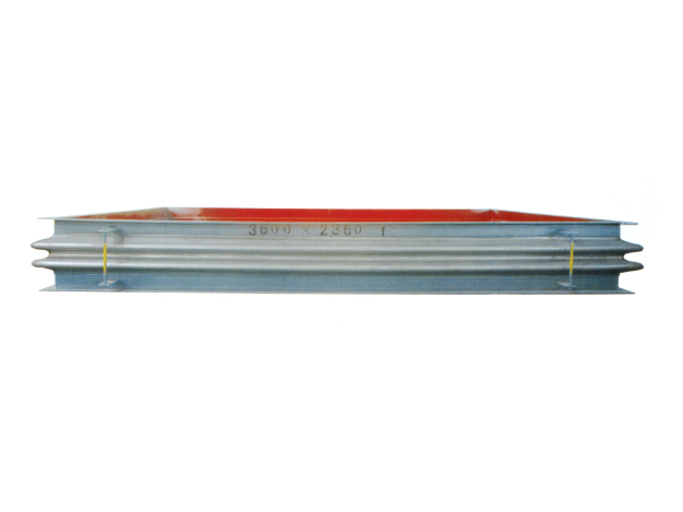
Metal rectangular expansion joint
Product introduction of metal rectangular expansion jointProduct Structure and C...
Learn more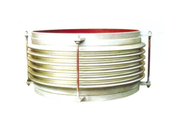
Universal corrugated expansion joint
The universal corrugated expansion joint is a kind of flexible compensation elem...
Learn more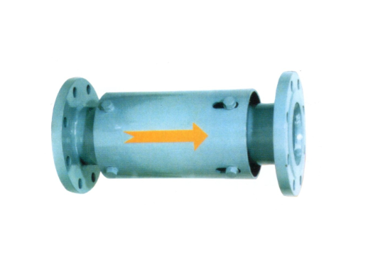
Single axial expansion joint
I. Structural compositionThe single axial expansion joint is mainly composed of ...
Learn moreCompensator, baffle door equipment · One-stop service process
From consultation to installation, we offer a full range of professional services
Consultation needs
The professional team will provide you with detailed product consultation and technical support to understand your specific needs
Scheme design
Provide personalized product design according to your specific needs to ensure the best solution
Manufacturing
Adopt advanced production equipment and technology and strict quality control to ensure excellent product quality
Installation and commissioning
Professional technicians provide on-site installation and commissioning services to ensure the normal operation of the equipment
About Us
Nantong Chuangxin Machinery Co., Ltd. is located in the plain of central Suzhou, close to Nantong and Ningjingyan Expressway with convenient transportation, and less than 2 hours drive from Shanghai, Suzhou, Wuxi, Nanjing and other large and medium-sized cities.
The company is a comprehensive scientific and technological enterprise integrating design and development, production, product sales, installation and debugging. The company has successively communicated and cooperated with the National Cement Research Institute and the general contractor!
The company's main products are metal compensator (expansion joint), non-metal compensator (expansion joint), baffle door and other series products, providing excellent and cheap complete sets of equipment for the majority of users at home and abroad.

NEWS
Stay up-to-date with company and industry updates
Service life of flue expansion joints in power plants: influencing factors and extension strategies
In the flue duct system of coal-fired power plants, gas-fired power pl...
How to weld flue expansion joints: A standard process and operation guide
In the installation and maintenance of flue system, welding is one of ...
Quality requirements for maintenance of flue expansion joints in power plants: Complete specifications and acceptance points
In the flue duct system of coal-fired power plants, gas-fired power pl...
Expansion joint at vertical section of desulfurization original flue: design, selection, operation and maintenance
In the wet desulfurization system, the vertical section of the origina...
Causes of water leakage in expansion joint of original flue of desulfurization: comprehensive diagnosis and solution
In the wet desulfurization system, the original flue conduit is respon...
Service Life of Clean Steel Flue Expansion Joints: Influencing Factors and Extension Strategies
In the flue gas treatment systems of iron and steel smelting, electric...
Frequently asked questions
Answers to your frequently asked questions about compensators and baffle doors
In the equipment management of industrial flue system, maintenance documents are the core basis for guiding on-site operation, ensuring maintenance quality and realizing process traceability. However, the operation and maintenance personnel of many power plants and chemical plants are not clear: What does the flue expansion joint overhaul document include? What should a complete overhaul document package contain to meet the standardized management requirements? This paper will systematically sort out the technical documents, management forms and acceptance data required for the maintenance of flue expansion joints, and provide practical checklist reference for equipment managers and maintenance engineers.
1. Classification framework of maintenance documents of flue expansion joints
To answer "What Does a Flue Expansion Joint Overhaul Document Include", you should first classify the documents from a functional point of view. In general, a complete overhaul document package can be divided into four main categories:
| Categories of Documents | Primary role | Examples of typical files |
|---|---|---|
| Technical specification category | Clear maintenance standards and process requirements | Maintenance procedures, drawings and equipment instructions |
| Scheme Plan Class | Guide specific work processes | Maintenance construction plan, safety measure plan, schedule |
| Process Record Class | Record the implementation of maintenance | Inspection record sheet, dimensional measurement record, defect ledger |
| Acceptance delivery class | Confirm overhaul quality and completion status | Quality acceptance document, test report, completion report |
The specific contents of each category of documents will be described in detail below.
Technical specification documents
This is the technical basis for the overhaul work, which must be fully prepared before the overhaul begins.
1. Technical specifications for maintenance of expansion joints
- Contents: Scope of application, reference standards (e.g. GB/T 12777, DL/T 782, etc.), maintenance cycle, maintenance items, quality requirements
- Requirements: It should be an official document prepared or quoted by this unit, and the version is currently valid
2. Equipment drawings and technical data
- Expansion joint body drawing: structure size, material, compensation amount, pressure grade
- Installation position diagram: specific position of the expansion joint in the flue system, connection mode, adjacent bracket arrangement
- Flue system diagram: flue gas flow direction, temperature measuring point, expansion center position
- Original design parameters: design temperature, pressure, displacement, service life
3. Manufacturer Technical Documents
- Product certificate and factory inspection report
- Installation and use instructions (including pre-tension/pre-compression requirements, bolt torque values)
- Spare parts list and recommended replacement period
4. Historical maintenance archives
- Completion report and replacement record of last overhaul
- Problems found in previous inspections and their handling
- Accumulated running time and starting and stopping times of expansion joint
Programme and Plan Documents
This part of the document answers the question of "how to carry out maintenance" and is a direct guidance for field operations.
1. Maintenance construction plan
The main contents include:
- Project Overview: Maintenance Scope, Main Workload, Planned Period
- Organizational measures: Division of labor between the person in charge of maintenance, safety officer and operator
- Technical measures: disassembly sequence, inspection items, installation process requirements
- Safety measures: shutdown isolation, ventilation, gas detection, personal protection, emergency plan
- Quality assurance measures: key quality control points, inspection methods
2. Safety risk analysis and control measures
- JSA/JHA Analysis Table: Analyze the risks of disassembly, hoisting, welding, pressure test, etc. item by item
- Risk Level Assessment: High, Medium and Low Risk Categories
- Control measures: preventive and emergency measures corresponding to each group of risks
3. Maintenance schedule
- Maintenance network diagram or Gantt chart
- Critical nodes: downtime, disassembly completed, inspection completed, reassembly completed, trial operation completed
4. List of spare parts and materials
- Spare parts list: expansion joint body (if replaced), gasket, bolt nut, guide tube
- Material list: welding materials, sealants, anti-corrosion coatings, insulation materials
- Tool list: torque wrench, hand hoist, gas detector, scaffold
IV. Process record files
What is included in the overhaul documents of flue expansion joints-Process record class is the core of overhaul "trace management" and the basis of quality traceability.
1. Inspection records before maintenance
- Appearance inspection record sheet (with photos)
- Record of leak test (if any)
- Raw dimensional measurements (expansion joint installation length, flue flange spacing)
2. Disassembly Process Record
- Record of fastener removal (rust condition, whether to replace)
- Record of damage of old expansion joint (crack, perforation, aging, deformation)
- Inspection record of flange surface (flatness, corrosion depth)
3. Critical process control records
| Procedure | Contents of records | Recording frequency |
|---|---|---|
| New expansion joint arrival inspection | Model verification, appearance inspection, flow direction identification confirmation | Each piece |
| Flange surface treatment | Photograph after cleaning, flatness measurements | Each flange |
| Pre-stretching/pre-compression | Actual pre-deformation amount, ambient temperature | Each expansion joint |
| Bolt tightening | Tightening sequence, torque value per pass | Each bolt |
| Welding (if applicable) | Welding process parameters and welder certification status | Each weld |
4. Defects and Handling Records
- Defect ledger: defect location, type (crack, corrosion, deformation, etc.), size, photo number
- Processing records: processing methods (grinding, repair welding, replacement, repainting, etc.), processing personnel, acceptance results
5. Maintenance log
- Daily homework content and completion progress
- Problems encountered and solutions
- Work plan for the next day
V. Acceptance and delivery documents
After the overhaul is completed, a series of confirmation documents need to be formed, marking the closed loop of the overhaul work.
1. Quality inspection/acceptance records
- Sub-item acceptance records: flange cleaning acceptance, expansion joint installation acceptance, bolt tightening acceptance
- Test Report:
- Airtightness test report (test pressure, holding time, pressure drop value)
- Where welding is involved: NDT report (PT, MT report)
- Level 3 acceptance signature form: team self-inspection → professional re-inspection → department final inspection
2. Completion report
Main content:
- Overview of Maintenance: Comparison between Planned and Actual Duration
- Main work content: List of replacement parts, handling of major defects
- Quality Evaluation: Acceptance Conclusions
- Remaining Issues and Suggestions: Note if there are any unaddressed issues
- List of attachments: Index of all process records
3. Trial operation records
- Inspection record of expansion joint condition after system start-up (with leakage or abnormal deformation)
- Displacement inspection record under hot condition (comparison of cold and hot dimensions)
- Operation Parameter Record (Temperature, Pressure)
4. Document Filing Checklist
What is included in a complete flue expansion joint overhaul document should ultimately be summarized in the form of a filed checklist:
- Maintenance construction plan (signed version)
- Safety Risk Analysis Table
- Drawings and technical data (stamped with "verified on site")
- Certificate of Spare Parts and Material Certificate
- Pre-maintenance inspection records and photos
- Process Control Record (Process Card)
- Defect Handling Ledger
- Maintenance log
- Quality Acceptance Document and Test Report
- COMPLETION REPORT
- Trial operation record
- Electronic version of scanned copy CD/folder
VI. Differences in documents of different types of expansion joints
What is included in the flue expansion joint overhaul documentation will vary slightly depending on the type of expansion joint:
| Expansion joint type | Special documents to be supplemented |
|---|---|
| Non-metallic fabric expansion joint | Material certification of fabric layer (temperature resistance, corrosion resistance), torque value table of platen bolts, instructions for use of repair glue |
| Metal bellows expansion joint | Color flaw detection or magnetic particle detection report, wall thickness detection record, bellows fatigue life assessment report (if applicable) |
| rubber expansion joint | Rubber hardness test records, swelling assessment |
| Lined PTFE expansion joint | EDM pinhole test report, liner adhesion test record |
Common Problems and Improvement Suggestions of Document Management
In actual maintenance, the following problems often occur in document management:
| Question | influence | Improvement measures |
|---|---|---|
| Drawings not updated before maintenance | Installation Dimensions Wrong | Establish a "loose leaf" management mechanism for drawings, and revise them after every overhaul |
| Post-signing of process records | Data distortion, untraceability | Adopt on-site process card system, sign upon completion |
| Photo unmarked | Failure to correspond to defects in later stage | Place rulers and position markers when taking pictures |
| Missing Acceptance Signature | Unclear responsibility | Set up the three-level acceptance signature column, missing items shall not enter the next link |
| Electronic version not backed up | File Loss | Complete electronic filing within 10 working days after completion of overhaul |
VIII. Summary
What does the maintenance document of flue expansion joint include? A set of standardized and complete maintenance document package should cover the whole process of "technical basis → operation instruction → process record → acceptance and delivery", which can be summarized as follows:
- Technical specification category: maintenance procedures, equipment drawings, manufacturer's documents, historical files-answer "what standard to repair"
- Plan category: construction plan, risk analysis, schedule, spare parts list-answer "how to repair it, who will repair it, what to repair it with"
- Process record category: inspection record, process control record, defect ledger, maintenance log-answer "what was repaired, what was found, and how to deal with it"
- Acceptance and delivery category: quality acceptance document, test report, completion report, trial operation record-answer "How is the repair and whether it is qualified"
Summary of core points:
- Documents are not the formalism of "finishing and replenishing", but the process control tool of overhaul quality. Each record serves as the basis for future failure analysis and life assessment.
- It is recommended to use the "package" management mode, where all the above documents are packed into a dedicated file box (or electronic folder) with a list of documents attached to the cover.
- For outsourced maintenance projects, Party A shall incorporate the "completeness and standardization of maintenance document package" into the contractor's assessment index.
- After the overhaul, the file package shall be filed within 15 working days, and the storage period shall not be less than two overhaul cycles (usually 8~10 years).
Mastering "what is included in the maintenance documents of flue expansion joints" is not only the basic skill of equipment managers, but also the basis for realizing preventive maintenance and whole life cycle management. A standardized and detailed maintenance document package can not only guide on-site operation, ensure maintenance quality, but also provide valuable analysis basis in case of failure. It is an indispensable link in the equipment management system of power plants and chemical plants.
During the installation and maintenance of flue system, the direction of expansion joint is often neglected by field personnel. Some people will ask: Is it okay to install the flue expansion joint backwards? The answer to this question is clear and unambiguous – absolutely not. Once the expansion joint is installed backwards, it will lead to the decrease of compensation ability and seal failure, and the damage of bellows, flue deformation and even safety accidents in the worst case. This paper will systematically analyze the serious consequences of reverse installation of flue expansion joint, the method of judging the direction and the correct installation requirements, and provide clear guidance for engineers and technicians.
1. Why do flue expansion joints have direction requirements?
To understand why the answer is no "Is it OK to install the flue expansion joint backwards?" First, we need to understand the directional design principle of the expansion joint.
Expansion joints are not perfectly symmetrical components. Whether it is a metal bellows expansion joint or a non-metallic fabric expansion joint, its internal structure includes directional elements:
- Guide barrel (liner barrel): This is the most important directional component inside the expansion joint. One end of the guide tube is fixed to the inlet side of the flue pipe, and the other end is free to expand and contract, and its function is to guide the flue gas to pass smoothly and prevent the high-speed dusty flue gas from directly washing the bellows or the fabric layer. The opening direction of the guide tube must coincide with the flow direction of the flue gas.
- Limit rod and hinge: Some expansion joints are equipped with directional limit rod or hinge structure, which can only withstand the displacement in a specific direction. Reverse installation will lead to limit failure.
- Sealing structure: The sealing layer of some expansion joints is designed with directionality, and the sealing effect is greatly reduced when installing in reverse direction.
- Drainage hole: The drainage hole set at the lowest point of the expansion joint has a fixed orientation. After being installed backwards, the drainage hole may be located at the high point, resulting in the condensate being unable to discharge.
Therefore, is it okay to install the flue expansion joint backwards? From the design principle, install backwards means that all directional functions are lost.
2. Serious consequences of reverse installation of flue expansion joint
If you forcibly install the expansion joint backwards, a series of problems will arise:
1. Deflector failure, bellows or fabric layer is washed out
This is the most immediate and serious consequence. After installation backwards, the fixed end of the guide tube is located on the outlet side, and the free end faces the inlet side. When the high-temperature dusty flue gas enters the expansion joint, the first thing that impacts is not the smooth surface of the guide tube, but the trough of the bellows or the wrinkles of the fabric layer directly.
Consequence:
- Metal bellows: wear and pitting within months, leading to smoke leakage
- Non-metallic fabric layer: fibers are scattered, peeled, and perforated
2. Decreased compensation
The hinge or tie rod of some expansion joints (e.g. hinge type, universal type) has directional force bearing characteristics. After installation backwards, the expansion joint cannot absorb the thermal displacement in the design direction, which may result in:
- The thermal expansion of the flue cannot be released, and the stress is transmitted to the support or equipment interface
- Expansion joint body is subjected to additional bending or torsional stress, accelerating fatigue failure
3. Condensate accumulation corrosion
Effective drainage can only be achieved when the drainage hole is located at the lowest point of the expansion joint. When installed backwards, the drain holes may be located on the sides or even high points, and the condensate cannot be drained and accumulates inside the expansion joint.
Consequence:
- Acidic condensate soaks the bottom of bellows for a long time, resulting in pitting and perforation
- Hydrolysis and bulging of inner layer of non-metallic expansion joint
- Winter freezing may swell and crack expansion joints
4. Degraded sealing performance
The flange sealing surface of some expansion joints is designed with a step structure with high inside and low outside, and the sealing gasket may not be pressed tightly when installed in reverse direction, resulting in leakage.
5. Significantly reduced service life
Combined with the above factors, is it okay to install the flue expansion joint backwards? If it is installed backwards, the expansion joint with the original design life of 5~8 years may have serious failure within 3~6 months, and its life will be shortened by more than 90%.
3. Direction identification methods of different types of expansion joints
To avoid installing backwards, you must first know how to judge the direction. The following are the directional identifications of common expansion joints:
1. Metal bellows expansion joint
| Identification method | position | Identification method |
|---|---|---|
| Flow direction arrow | On the side of the flange or guide tube | The direction of the arrow is the flow direction of the flue gas |
| Guide tube observation | Viewed from the end of the flange | The fixed end of that guide tube is the inlet side, and the free end is the outlet side |
| Nameplate annotation | Expansion joint body nameplate | Mark "IN" and "OUT" |
| Drain hole location | Low point of expansion joint | The drain hole should be directly below after installation |
2. Non-metallic fabric expansion joint
Non-metallic expansion joints are likewise directional:
- The fixed end of the inner guide tube is pointed to the inlet side
- The overlapping direction of the multilayer composite fabric is usually pressed from the inlet side to the outlet side
- Some products have built-in anti-scour baffles with baffle openings facing the entrance
3. Rubber expansion joint
Rubber expansion joints usually have reinforcing rings or limiting rings, which should be installed on the side with higher pressure (i.e., the inlet side).
Fourth, how to correctly install flue expansion joint?
After mastering the direction recognition, the correct installation process is as follows:
Step 1: Check Before Installation
- Confirm the model, specification and pressure level of the expansion joint by comparing with the drawings
- Check that the direction of the flow direction arrow or guide tube is consistent with the design flow direction of the flue
- Record ambient temperature at installation and calculate pre-stretch/pre-compression amount
Step 2: Location and temporary fixation
- Hoist the expansion joint in place so that the flow direction arrow points in the direction of flue gas flow
- Preliminary fixing with temporary bolts or spot welding (metal expansion joints only)
- Check that the drain hole is directly below (vertical flue) or at the lowest point (horizontal flue)
Step 3: Pre-stretch or pre-compress
- Pre-deformation according to design values. If not specified in the design, the pre-stretch can be performed at 50% of the thermal displacement
- Use special stretching devices, and barbaric operation with crowbars is strictly prohibited
Step 4: Fasten the connection
- For flanged connections: Tighten bolts in diagonal sequence 3 times (30% → 70% → 100% torque)
- For welded joints: Symmetric segment welding is used to control weld deformation
Step 5: Check after installation
- Verify that the flow direction arrow is consistent with the flue flow direction
- Verify that the drain hole is at the lowest point and is clear
- Measure the actual installation length of the expansion joint and record it
5. What if it has been installed backwards?
In actual engineering, there is indeed a case where the expansion joint is installed backwards. Once discovered, it should be treated immediately:
Judge whether it can be adjusted
- Shutdown Maintenance Stage: Remove the equipment immediately if reaction is found, and reinstall it in the correct direction
- In-Operation Discovery: Assess leaks and safety risks. If there is no serious leak, it can be planned to adjust at the latest shutdown; If there is obvious leakage or scouring sound, stop the machine immediately
Adjustment steps
- System shutdown, cooling, ventilation, energy isolation
- Removing expansion joint connecting bolts or cutting welds
- Clean the flange surface and check whether the expansion joint body has been damaged
- If the expansion joint is intact, reinstall it in the correct direction
- If erosion wear or corrosion has occurred, replace the expansion joint with a new one
Special attention
Is it OK to install the flue expansion joint backwards? If it has been running for a period of time after being installed backwards, even if the appearance is intact, the internal guide tube may have been deformed or worn. It is recommended to replace it instead of reuse it, so as to avoid leaving hidden dangers.
VI. Clarification of common misunderstandings
| Misunderstanding | fact |
|---|---|
| "The expansion joint looks symmetrical, and it doesn't matter whether it is positive or negative" | The internal guide tube and limit structure are directional and absolutely asymmetric |
| "Non-metallic expansion joints have no direction" | The non-metallic expansion joint also has a guide tube and an overlap direction |
| "If you install it backwards, you can use it. At worst, you can change it in advance." | After reverse installation, it may suddenly break in a short time, causing shutdown and accident |
| "Small diameter expansion joints do not require tube orientation" | The smaller the diameter, the higher the scour speed and the more important the directionality |
| "It doesn't matter if the low-pressure flue is installed backwards" | Low pressure is not equal to no pressure, corrosion and condensation problems still exist |
VII. On-site inspection list
To ensure that there is no reverse installation problem, it is recommended to use the following checklist on site:
- Is the expansion joint flow direction arrow consistent with the flue design flow direction?
- Is the fixed end of the guide tube facing the direction of flue gas flow (inlet side)?
- Is the drain hole located at the lowest point of the expansion joint (directly below or at the bottom)?
- Is the "IN" end on the nameplate connected upstream of the flue and is the "OUT" end connected downstream?
- Has the flow confirmation been recorded in the installation record?
- Has a photo been taken to preserve, containing a photo where the flow direction arrow is clearly visible?
VIII. Summary
Is it OK to install the flue expansion joint backwards – the answer is no. The reverse installation of the expansion joint is a serious but completely avoidable mistake, and its consequences include: the failure of the guide tube leads to the erosion and perforation of the bellows or fabric layer, the accumulation and corrosion of condensate, the degradation of sealing performance, the loss of compensation ability, and finally the expansion joint is scrapped in a very short time, and even causes flue damage and safety accidents.
Core conclusions:
- Directionality cannot be ignored: the guide tube, limit structure, drainage hole, etc. inside the expansion joint are all designed with directionality, and the positive and reverse installation functions are hugely different
- The identification method is simple and reliable: flow direction arrow, guide tube observation, nameplate marking, drain hole position-confirm any two of them before installation to ensure the correct direction
- Installation specifications must be implemented: flow alignment, drain hole facing down, and diagonal fastening of bolts, which are the key control points to prevent reverse installation
- It must be corrected if it is installed backwards: after it is found that it is installed backwards, it should be shut down and adjusted as soon as possible; If it has been running for a period of time, it is recommended to replace it directly to ensure safety
- Training and acceptance are key: Incorporate "directional confirmation" into installation instructions and third-level acceptance items to eliminate reverse installation incidents from the management level
For on-site installers and maintenance engineers, remember one sentence: it is better to spend an extra minute confirming the direction than to pay ten times the price for installation. Be sure to strictly perform the flow-direction inspection procedure during every expansion joint installation or replacement operation-because once the flue expansion joint is installed backwards, the consequences are by no means as simple as "make do".
In industrial flue system, the expansion joint is exposed to high temperature, high humidity, harsh flue gas environment containing acid and sulfur for a long time, and corrosion problem has always been the main factor affecting its service life. So, how to prevent the flue expansion joint from corrosion? This is a common concern of operation and maintenance personnel in many power plants, steel mills and chemical enterprises. Effective anti-corrosion treatment can not only prolong the replacement period of expansion joint, but also avoid environmental protection exceeding standard and safety accidents caused by corrosion leakage. This paper will systematically introduce the corrosion mechanism, anti-corrosion method and construction technology of flue expansion joint, and provide practical guidance for field technicians.
First, why should the flue expansion joint be prevented from corrosion?
To understand how to prevent corrosion of flue expansion joints, first of all, we need to clarify the hazards of corrosion. The types of corrosion faced by flue expansion joints mainly include:
- Acid dew point corrosion: SO₃ in flue gas combines with water vapor to form sulfuric acid, which condenses when the temperature is lower than the acid dew point, causing strong corrosion to the metal expansion joint
- Pitting and crevice corrosion: Halogen ions such as chloride ions form local corrosion pits on the surface of stainless steel
- Stress corrosion cracking: brittle cracking of metal occurs under the combined action of tensile stress and corrosive medium
- High-temperature oxidation: When exceeding 400℃, the oxide scale on the surface of ordinary stainless steel peels off
- Aging of non-metallic materials: hydrolysis, cracking, swelling of rubber or fabric layers
Expansion joints without anti-corrosion treatment may leak in just a few months under corrosive working conditions, which seriously affects the system operation. Therefore, it is of great engineering value to master how to prevent corrosion of flue expansion joint.
2. Anticorrosion method of metal expansion joint
Metal expansion joints are the most common types, and their anti-corrosion measures can be divided into two categories: material selection and surface protection.
Material selection (preservation from source)
| Operating condition | RECOMMENDED MATERIAL | Corrosion resistance |
|---|---|---|
| General acidic flue gas (temperature ≤200℃) | Stainless steel 304 | Foundation corrosion resistance |
| Wet flue gas containing SO₂ and SO₃ | Stainless steel 316L | Contains molybdenum and has excellent acid corrosion resistance |
| High chloride environment (e.g. waste incineration) | 254SMO, C276 Hastelloy | Extremely strong pitting resistance |
| High temperature oxidizing flue gas (> 400℃) | 309S, 310S | High temperature oxidation resistance |
| Seawater flue gas (coastal power plant) | Super Duplex Stainless Steel | Resistance to chloride ion stress corrosion |
Surface coating protection
When the substrate has been identified or requires additional protection, coating corrosion protection can be applied:
1. Glass flake coating
- Features: Contains glass scales, forming a labyrinth effect, hindering the penetration of corrosive media
- Thickness: 1.5~3mm
- Applicable temperature: ≤150℃
- Application Method: Spray or Hand
2. High temperature acid-resistant coatings
- Features: Silicone modified resin, can withstand 200~300℃
- Applicable working conditions: medium temperature flue expansion joint
- Application method: Air spraying or brushing
3. Enamel (enamel) coating
- Features: Inorganic vitreous coating, high hardness, excellent acid resistance
- Applicable temperature: ≤450℃
- Construction method: High temperature sintering after dipping or spraying
4. Thermal Spray Metal Coating
- Features: Arc or flame sprayed aluminum, zinc or their alloys
- Function: Cathodic protection + physical shielding
- Applicable working conditions: Low-cost anti-corrosion scheme for carbon steel expansion joint
3. Anti-corrosion design of non-metallic expansion joint
Non-metallic expansion joints themselves are manufactured with corrosion-resistant materials, but their anti-corrosion emphasis lies in structural design and material selection.
Material selection principle
| Corrosive media | Recommended flexible materials | Materials not recommended |
|---|---|---|
| SO₂-containing wet flue gas (pH 2~5) | Fluororubber, PTFE | Neoprene rubber |
| Strong oxidizing flue gas containing NOx | PTFE | EPDM rubber |
| Oily flue gas | fluororubber | Silicone rubber |
| Chlorine-containing flue gas (HCl) | PTFE, fluororubber | Ordinary rubber |
Structural anti-corrosion design
How to prevent corrosion of flue expansion joints? Among non-metallic types, structural design is crucial:
- The stainless steel guide tube extends to the inside of the expansion joint to prevent smoke from directly washing and soaking the flexible fabric layer
- Add drainage holes: Open drainage holes at the lowest part of the expansion joint to avoid condensate accumulation
- Thermal insulation layer protection: the inner ceramic fiber layer can reduce the outer surface temperature and reduce the outer wall condensation corrosion
- Flange seal optimization: Acid-resistant rubber gasket is used, and sealant is applied to prevent gap corrosion
4. Anticorrosion construction technology of flue expansion joint
The following is the most commonly used anti-corrosion construction process when making or repairing expansion joints on site, and answers the practical question of "how to prevent corrosion of flue expansion joints" for you.
Step 1: Surface Treatment (Rust Removal)
The anti-corrosion effect is 70% dependent on the quality of the surface treatment:
- Sandblasting treatment: reach the standard of Sa2.5, the surface is gray-white metallic luster, and the roughness is 40~70 μ m
- For small area repair: Angle grinder with wire brush can be used to grind to St3 grade
- Oil removal: Wipe with solvent to remove oil and salt
Step 2: Apply Primer
Primer selection according to working conditions:
- Epoxy zinc-rich primer (Zn content ≥70%): suitable for carbon steel expansion joints
- High temperature primer (e.g. inorganic zinc silicate): suitable for medium to high temperature expansion joints
- Coating thickness: 40~60 μ m
Step 3: Intermediate coating and top coating construction
- Intermediate coating: epoxy cloud iron intermediate paint, thickness 80~120 μ m, enhanced shielding effect
- Top coat: Weather or acid resistant top coat, thickness 50~70 μ m
- Total dry film thickness: ≥200 μ m in general working conditions, ≥300 μ m in severe corrosion conditions
Step 4: Quality inspection
- The wet film thickness gauge measures the thickness of each coating
- EDM leak detector detects pinhole (voltage 2000V, no alarm is qualified)
- Adhesion test: cross-grid or pull-apart
V. Anti-corrosion strategies under different working conditions
| Type of operating condition | Typical industries | Recommendation of anti-corrosion scheme |
|---|---|---|
| High temperature and low corrosion (300~500℃, low sulfur content) | Steel hot air duct | Material upgrade (310S) + uncoated or high temperature paint |
| Medium temperature acidic (120~200℃, containing SO₂) | Original flue of power plant | Material 316L + glass flake coating (optional) |
| Low temperature and high humidity (50~80℃, pH 2~3) | Clean flue after desulfurization | Non-metallic expansion joints (fluororubber) are preferred |
| High temperature with chlorine (> 200℃, with HCl) | Waste incineration | Lined with PTFE metal expansion joint or C276 alloy |
| Abrasion + Corrosion | Catalytic cracking flue gas | Wear-resistant lining + heat-resistant stainless steel double protection |
VI. Common causes and prevention of anti-corrosion failure
Even if you know how to prevent the flue expansion joint from corrosion, sometimes early failure still occurs. The main reasons include:
| Failure phenomenon | Root cause | Precautionary measures |
|---|---|---|
| Coating blistering and shedding | Surface treatment is not thorough, leaving oil or rust | Strictly blasted to grade Sa2.5, immediate coating |
| Coating pinhole corrosion | Too thin or missing coating | Increase the number of coatings, electric spark detection |
| Preferential corrosion at weld | Microstructure change in welding heat-affected zone | Passivation treatment or zinc-rich primer after welding |
| Corrosion of fluid accumulation in trough of expansion joint | No drainage hole | Open drainage holes and clean them regularly |
| Crack of outer layer of non-metallic expansion joint | UV or Ozone Aging | Install protective cover and apply protective oil regularly |
Anticorrosion during maintenance period and extension of service life
In addition to the corrosion protection of newly made expansion joints, maintenance and corrosion protection during operation are equally important:
- Regular cleaning: Remove dust, especially corrosive dust, from the surface of the expansion joint
- Repairing: If the coating is found to be scratched or peeled off, polish and repaint in time
- Drain hole inspection: dredge once a month to prevent condensate accumulation
- Bolt anti-corrosion: Apply high-temperature anti-bite agent to flange bolts to prevent rust death
- Record corrosion rate: measure expansion joint wall thickness annually to assess corrosion trend
VIII. Summary
How to prevent corrosion of flue expansion joint needs to be systematically answered from four levels: material selection, structural design, surface treatment and operation and maintenance. The core conclusions are as follows:
- Material selection is the basis: select suitable metal or non-metal materials according to flue gas temperature, acid dew point and chloride ion concentration. 316L stainless steel is suitable for most acidic wet flue gas, and fluororubber non-metallic expansion joint is the preferred flue after desulfurization
- The coating is a barrier: for metal expansion joints, sandblasting + epoxy zinc-rich primer + epoxy cloud iron mid-coat + acid-resistant top coat with a total thickness ≥200 μ m can significantly extend the service life
- Structural design is key: deflectors prevent direct flushing and drainage holes avoid accumulation of fluid — both designs are more effective than any coating
- Construction quality determines success or failure: Surface treatment should reach Sa2.5 grade, temperature and humidity should be controlled in coating process, and EDM pinhole inspection should not be omitted
- Maintenance is the guarantee: Regular cleaning, repainting and dredging of drainage holes can prolong the service life of expansion joints by 30% ~50%
Through the systematic anti-corrosion scheme, the service life of metal expansion joints can be extended from 1~2 years to 5~8 years, and that of non-metal expansion joints can reach 6~10 years in acidic wet flue gas conditions. For operation and maintenance personnel, mastering "how to prevent corrosion of flue expansion joints" is not only a technical ability, but also an important means to reduce spare parts costs and unplanned downtime.
In the daily operation and maintenance and regular maintenance of industrial flue system, expansion joint, as a wear part, will have problems such as aging, leakage or decreased compensation ability after long-term operation, so it needs to be replaced in time. So, how to remove the expansion joint in the flue? This is a practical problem that many field engineers and overhaul workers often face. It seems simple to remove the expansion joint, but if it is not operated properly, it may not only damage the flue interface, but also pose a great safety hazard. This paper will systematically explain the disassembly method, preparation work, operation steps and matters needing attention of the expansion joint in the flue, and provide practical guidance for the field operation.
First, why do you need to know the disassembly method of the expansion joint in the flue?
Before starting the discussion "How to remove the expansion joint in the flue", it is necessary to clarify the circumstances under which the expansion joint needs to be removed:
- Damage to the expansion joint body: cracks, perforations, bulging or severe aging, resulting in flue gas leakage
- Achieve the designed service life: Non-metallic expansion joints are usually 5~8 years, and metal expansion joints need to be replaced 8~12 years
- System retrofit and upgrade: flue routing change or replacement of different types of expansion joints
- Internal maintenance requires: cleaning up dust accumulation, checking the guide tube or replacing the insulation layer
Whatever the reason, mastering the correct disassembly method can effectively shorten the downtime, avoid secondary damage and ensure the safety of workers.
Preparation before disassembly
The first step in how to remove the expansion joint in the flue is to be fully prepared. Do not work blindly, otherwise it may cause safety accidents or equipment damage.
1. Safety measures
- Shutdown Cooling: Ensure that the flue system has been completely shut down and the internal temperature has dropped below 50℃
- Ventilation replacement: Forced ventilation of flue to eliminate residual toxic and harmful gases (such as CO, SO₂)
- Energy isolation: Cut off the fan power supply and lock the tag (LOTO), close the upstream and downstream baffle doors
- Gas detection: Use four-in-one gas detector to confirm oxygen content (19.5% ~23.5%) and no toxic gas
2. Preparation of tools and materials
| Tool Category | Specific items |
|---|---|
| Hand tools | Wrenches, sockets, screwdrivers, crowbars, hand hammers |
| Cutting tool | Angle grinder (with cutting blade), gas cutting equipment (metal expansion joint only) |
| Lifting equipment | Hand-pulled hoist, hoisting belt, jack |
| Protective Equipment | Dust mask, goggles, high temperature gloves, safety helmet, safety belt |
| Auxiliary materials | Marker pen, camera (record original condition), sealant, plugging mud (spare) |
3. Site Investigation and Marking
- Take photos to record the original condition of the expansion joint before installation
- Mark the relative position of the expansion joint to the flue (may be aligned with sample punch or paint at the flange)
- Check whether there is dust accumulation on both sides of the expansion joint, and clean it in advance if so
Third, step-by-step explanation: How to remove the expansion joint in the flue?
The following is a standard disassembly process for the most common flanged expansion joints.
Step 1: Clean the area around the expansion joint
Use a blade or compressed air to remove dust, corrosion and debris from both ends of the expansion joint and flange bolts. Pay special attention to cleaning the blockage in the bolt hole to avoid the bolt jamming during disassembly.
Key points: Wear a dust mask during cleaning to prevent inhalation of flue dust containing heavy metals.
Step 2: Remove the insulation layer and outer guard
If the outside of the expansion joint is covered with insulation layer and outer guard plate, it needs to be removed first:
- Use a screwdriver or driver to remove the outer guard fixing screws
- Carefully remove the outer guard plate to avoid deformation
- Clean the heat preservation cotton to expose the connection part between the expansion joint body and the flue
Step 3: Remove the connecting bolts
The core step of how to remove the expansion joint in the flue is to remove the flange connecting bolt:
- First, try to loosen the first bolt with a wrench. If the rust is serious, spray loosening agent (WD-40, etc.) and wait for 10~15 minutes
- Loosen all bolts gradually in diagonal order to avoid flange deformation caused by eccentric load
- For bolts that are rusted and cannot be loosened, the following methods can be used:
- Angle grinder cutting nut
- Acetylene flame heating (metal flanges only, and pay attention to fire protection)
- Hydraulic nut splitter
Note: The removed bolts and gaskets should be placed in order, and anti-rust treatment should be done if reuse is planned.
Step 4: Separate the expansion joint from the flue flange
After all the bolts are removed, the expansion joint and the flue flange may not be separated due to rust or sealant sticking:
- Gently insert a crowbar into the flange gap and pry it evenly around
- If it still cannot be separated, gently tap the edge of the flange with a hand hammer and a copper rod (it is prohibited to directly tap the expansion joint body)
- For firmly bonded non-metallic expansion joints, use a utility knife to cut the sealant along the flange surface
Step 5: Lift or remove the expansion joint
Select the appropriate removal method according to the weight and installation position of the expansion joint:
- Small expansion joint (
- Medium expansion joint (50~200kg): lifted by hand hoist or forklift
- Large expansion joint (> 200kg): crane is required and center of gravity position is calculated in advance
Safety reminder: It is strictly forbidden to stand under heavy objects during lifting. Although the non-metallic expansion joint is light, it is large in volume and easy to deform. When hoisting, a wide sling should be used to avoid the rope strangling the flexible body.
Step 6: Check the flue flange interface
After the expansion joint is removed, do not rush to install new parts. You should first check:
- Whether the flange surface is smooth and there are corrosion potholes
- Whether the bolt hole is deformed or the thread is damaged
- Is the flow guide tube inside the flue intact
If there are defects, they need to be repaired first (sanding, repair welding, tapping, etc.).
4. Disassembly differences of different types of expansion joints
How to remove the expansion joint in the flue will vary slightly depending on the type of expansion joint:
| Expansion joint type | Disassembly Features | Special precautions |
|---|---|---|
| Flanged non-metallic expansion joint | Simpler and lighter | Pay attention to protecting the flexible cloth to avoid scratches |
| Flanged metal expansion joint | Bolt corrosion is common and requires loosening agent or cutting | Bellows are thin-walled and vulnerable, and should not be knocked |
| Welded connection expansion joint | Complicated, need to cut weld | Welding qualification required, leave grinding allowance after cutting |
| Plug-in expansion joint | The pressure plate and sealing packing need to be removed first | Pay attention to the recycling of fillers (may contain asbestos) |
For the welded expansion joint, the answer to "How to remove the expansion joint in the flue" involves cutting operation: use gas cutting or plasma cutting to cut along the edge of the weld, and pay attention to controlling the cutting depth to avoid damaging the flue base metal.
5. Common problems and coping strategies
Problem 1: The bolts are all rusty and cannot be removed
Response: Cut nuts in batches and replace new bolts. It is not recommended to forcibly use a large wrench afterburner, which can easily lead to bolt breakage or flange damage.
Problem 2: The expansion joint is stuck in the flange and cannot be removed
Response: Check for hidden weld spots or retaining pins. If not, use a three-jaw pull horse or mechanical jack to eject from the inside.
Problem 3: Nonmetallic expansion joint flexible cloth is aged and broken
Response: The flexible cloth may tear itself when removed, which is normal. However, care should be taken to clean up all debris to avoid leftovers entering the flue.
Question 4: Difficulty working at height
Response: It is necessary to set up a reliable working platform or use a lift truck, and 100% of the operators should wear seat belts. Operations should be stopped in bad weather (strong wind, rain and snow).
Safety Reminders and Environmental Protection Requirements
- Anti-scald: Even if the machine is stopped for cooling, the temperature of the flue wall may still be higher than 80℃, and high-temperature-resistant gloves should be worn when contacting
- Anti-asphyxiation: There may be oxygen deficiency or nitrogen replacement residue in the flue, and continuous ventilation and gas detection must be made
- Fire and explosion prevention: Clean up combustible materials before cutting operations and equip fire extinguishers. If gas has been conveyed into the flue, it must be thoroughly purged
- Environmental protection disposal: Scrapped expansion joints (especially non-metallic composite cloth) shall be disposed of according to industrial solid waste classification and shall not be discarded at will
VII. SUMMARY
Regarding the practical problem of "how to remove the expansion joint in the flue", the core points can be summarized as follows:
- Safety priority: shutdown, cooling, ventilation, gas detection and energy isolation are indispensable, which is the prerequisite of all disassembly operations
- Sufficient preparation: cleaning, marking, tools in place, protective wear, on-site investigation to understand the type of expansion joint and connection method
- Disassembly sequence specification: cleaning → removing heat insulation → loosening bolts (diagonal) → separating flanges → lifting and removing, each step has specific skills
- Classification: Flange connection type is the most common, just follow the above steps; Welded type needs to be cut; Plug-in type needs to remove the pressure plate first. Different types of expansion joints have different answers to "How to remove expansion joints in flue"
- Flange inspection is indispensable: after removing the old parts, the condition of the flange surface must be checked and repaired if necessary, otherwise the new expansion joint may still leak after installation
- Team cooperation: Disassembly operation requires at least 2~3 people to cooperate, one person to operate and one person to monitor, and command signal is required in lifting process
Mastering the correct disassembly method can not only safely and efficiently complete the replacement work of the expansion joint in the flue, but also protect the flue interface from being intact, thus laying a good foundation for the subsequent installation of new expansion joint. It is recommended that the above-mentioned procedures be prepared as an operation instruction, and special training should be carried out for maintenance personnel to ensure that every disassembly operation is standardized, safe and reliable.
In the technical exchange of industrial pipelines and flue gas treatment systems, the terms "shock absorber", "expansion joint" and "compensator" are often heard overlapping. Someone asked: Is the expansion joint installed at the inlet and outlet of the fan? What exactly should that fabric soft connection in the flue be called? Therefore, the question "Is the flue shock absorber the expansion joint?" has become the common doubt of many technicians. Their functions do overlap, but strictly speaking, they are two concepts in different dimensions, intersecting but not equivalent. This article will help you clarify these two concepts thoroughly, from functional positioning, structural principles to practical applications.
1. Functional analysis: the core task of expansion joint and shock absorber
To answer "Is the flue shock absorber an expansion joint?", we should first dismantle it from the most essential function:
- Expansion Joint (Compensator): The core task is thermal displacement compensation. When the pipeline transports high-temperature steam or flue gas, the pipe wall will elongate (thermal expansion and contraction) when heated. If there is no flexible link, huge thermal stress will crack the pipeline or equipment. The expansion joint is the use of its corrugated structure or fabric material to absorb the thermal expansion and contraction of the pipe。
- Flue Shock Absorber: The core task is to absorb shock and noise. The operation of equipment (such as fans) will generate high-frequency mechanical vibrations. If not blocked, these vibrations will be transmitted along the rigid flue steel plate to the whole building, which will not only disturb the people with noise, but also cause fatigue damage to the pipe connections. The original intention of the shock absorber is to cut off the propagation path of vibration。
From this dimension, the expansion joint is "mainly inside"-to resolve thermal stress; Shock Absorber "Main Outer"-Isolates mechanical vibrations. The focus of the two is not exactly the same.
2. Shock absorption and compensation: overlapping functions on rubber expansion joints
Since the expansion joint and the shock absorber have different functions, why do people still ask "Is the flue shock absorber the expansion joint"? Because in engineering practice, there is one product that perfectly blends the functions of the two, and this is the rubber compensator.
Rubber compensator (aka rubber expansion joint, flexible rubber joint, shock absorber, pipe shock absorber, shock throat), the name itself reflects its dual identity.
- Structural realization: It is composed of high elasticity rubber sphere and metal flange. The rubber itself has good vibration absorption and damping characteristics, which can greatly reduce noise。
- Displacement compensation: At the same time, it makes use of the flexibility of rubber to compensate the trace axial expansion and contraction of the pipeline and the discentricity (i.e., lateral displacement) during installation.
In this particular category, the role of the expansion joint (to compensate for displacement) is combined with the role of the shock absorber (to absorb shock and noise). Therefore, when the technician points to the rubber compensator and says "this is the flue shock absorber", this answer holds true in the specific context.
3. Non-metallic expansion joint: the "flexible all-around champion" in the flue
Apart from rubber, another structure that is more common in smoke and air systems is a non-metallic expansion joint (also known as a fabric compensator). Returning to the question "Is the flue shock absorber an expansion joint?", we can see more adequate evidence on non-metallic expansion joints.
Non-metallic expansion joints are mainly composed of flexible materials such as fiber fabric, silicone cloth, fluorine adhesive cloth and thermal insulation cotton。 Its construction is perfectly suited to the needs of "shock absorption":
- Seismic isolation function: Fiber fabric and insulation cotton itself have sound absorption and vibration isolation functions, which can effectively reduce and eliminate the transmission of noise and vibration in boiler, fan and other systems。
- Compensation displacement: It can provide large multi-dimensional direction compensation in a smaller size range and absorb the thermal displacement of the pipe。
The thrust-free characteristic is the key feature to distinguish: because the main material is fiber fabric, the non-metallic expansion joint has weak transmission (no reverse thrust) when it runs. This means that it can easily cut off the conduction of equipment vibration to the pipe system, which is not possible with metal hard connections。 Therefore, installing non-metallic expansion joints at the inlet and outlet of the fan completely plays the physical effect of "shock absorber" in actual engineering.
4. Concept analysis: how to accurately select according to the scene
Although the expansion joint often covers the demand of shock absorption in function, the two still have different emphases in engineering selection. To help you sort out "Is the flue shock absorber an expansion joint?", the following table shows the typical configuration in different scenarios:
Note: Although pure metal corrugated expansion joint is also called expansion joint, it mainly absorbs heat displacement by metal corrugated deformation, and its vibration isolation effect is far inferior to that of rubber or fabric. If pure metal expansion joints are selected only for "shock absorption", the effect may not be satisfactory.
V. Summary: Is the flue shock absorber the expansion joint? The key depends on the occasion
At this point, a clear conclusion can be given for the question "Is the flue shock absorber an expansion joint?"
"Flue shock absorber" is a function that expansion joints implement in a specific scenario, and it can't be said that all expansion joints are shock absorbers.
- When the expansion joint uses rubber or fiber fabric as the main material (such as rubber compensator and non-metallic fabric compensator), it naturally has excellent seismic isolation and noise absorption function. In this context, it is the ideal flexible shock absorber for flue systems。
- When the expansion joint is a pure metal bellows structure, it is mainly used to absorb heat displacement, and the vibration isolation effect is weak. At this time, it is not appropriate to call it a shock absorber。
Selection suggestion: For the vibration and noise problems of fans and flues, non-metallic fabric compensator or rubber air duct compensator should be preferred; Aiming at the problem of thermal expansion of high temperature steam pipeline, the metal corrugated compensator is selected with the guide bracket.
Contact Us
Your consultation and cooperation are always welcome
Company Address
Haian Economic and Technological Development Zone, Nantong City, Jiangsu Province
Contact Number
13142668488
info@jsbcq.net
Working hours
Monday-Friday :8:00 - 17:30
Saturday :9:00 - 16:00
Sunday :Rest